
Solar Carport Mounting System
Easy Solar manufactures solar carport mounting system solutions for commercial parking lots, residential parking spaces, EV charging stations and PV canopy projects. Our factory-direct solar carport racking, carport frame for solar panels and PV carport canopy structures can be customized according to parking layout, module size, span, clearance height, waterproof requirements, wind load, snow load and foundation conditions.
- Commercial Parking Lots
- EV Charging Stations
- Waterproof Options
- Custom Span & Clearance
- OEM / ODM Available
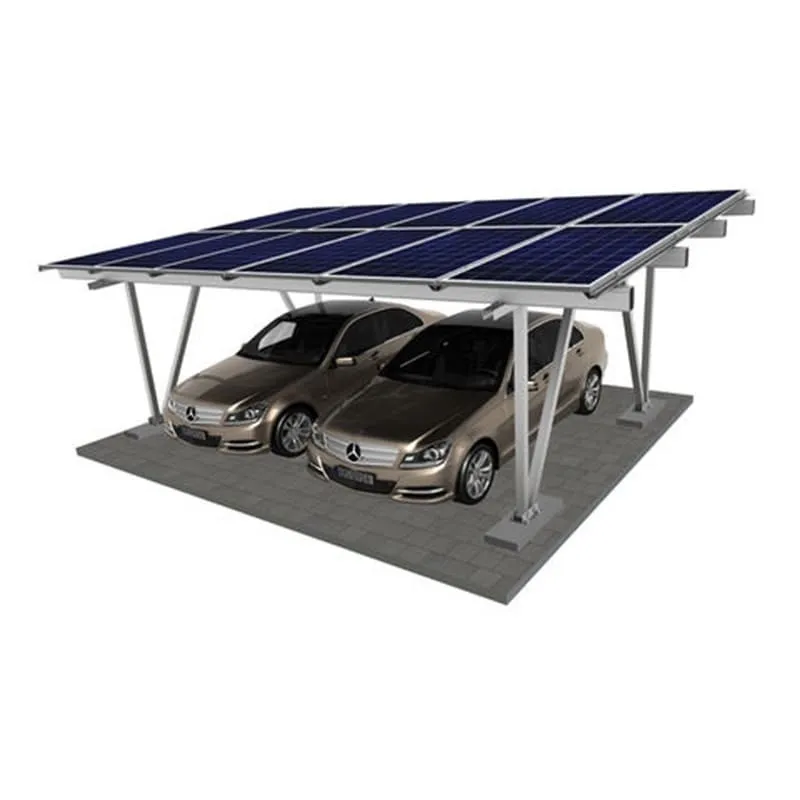
Choose the Right Solar Carport Mounting System
Compare our main solar carport solutions by project requirement. Choose a waterproof PV canopy when rainwater control is important, a commercial system for larger parking lots and EV charging projects, or a residential system for home and villa parking.
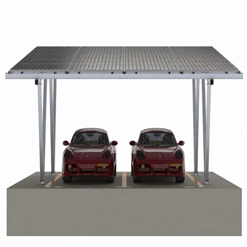
Waterproof Solar Carport Mounting System
For waterproof solar carport structures, drainage channels, water guide rails, PV canopy sealing and rain protection requirements.
View Waterproof Carport →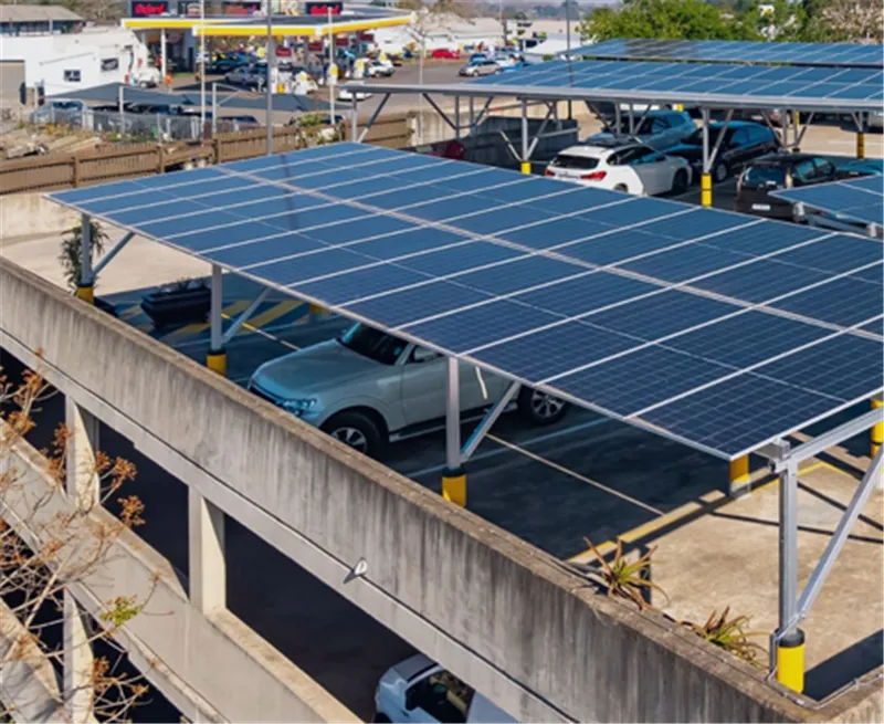
Commercial Solar Carport Mounting System
For commercial parking lots, office parks, schools, hospitals, shopping centers, industrial sites, EV charging stations and large-scale PV canopy projects.
View Commercial Carport →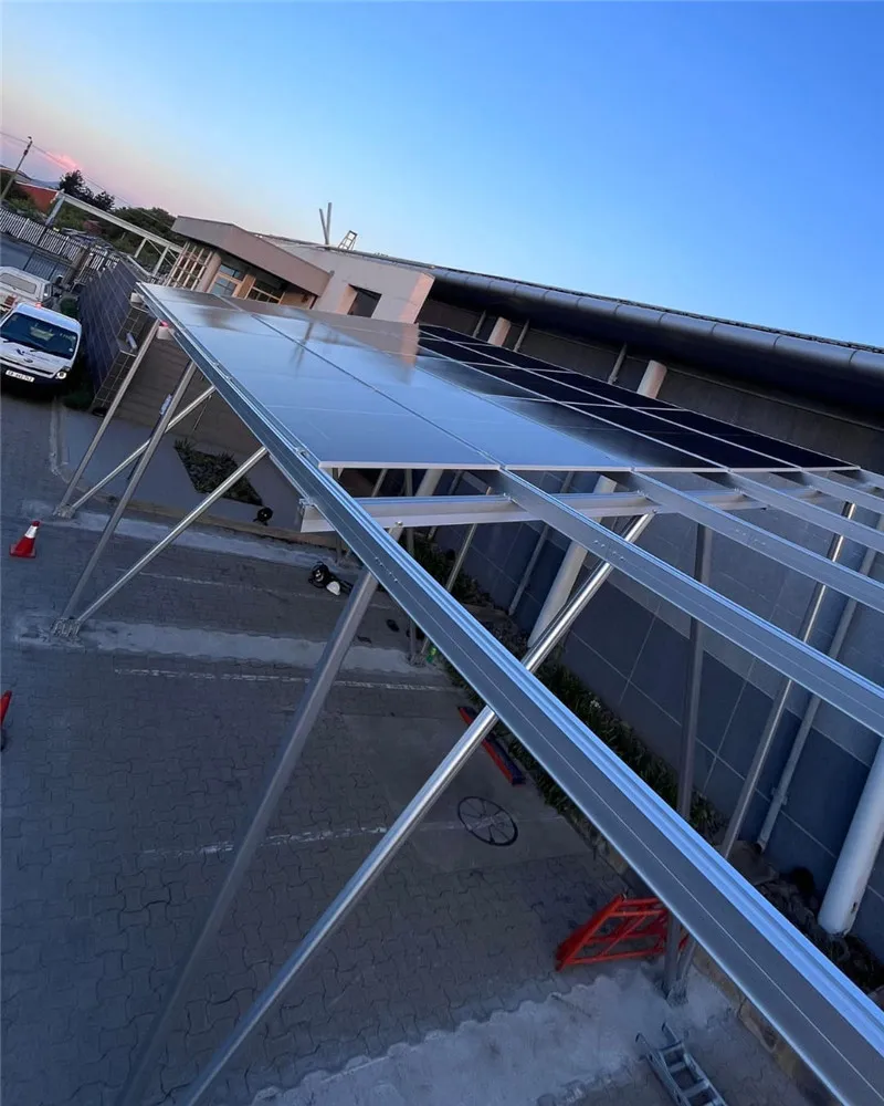
Residential Solar Carport Mounting System
For home parking spaces, villas, 1-car and 2-car carports, small distributed PV projects and residential solar canopy structures.
View Residential Carport →Solar Carport Applications for Parking and PV Projects
Solar carport projects combine parking protection, clean power generation and efficient land use. Easy Solar supports commercial parking lots, residential spaces, EV charging stations and waterproof PV canopy projects with project-specific structure and component configurations.
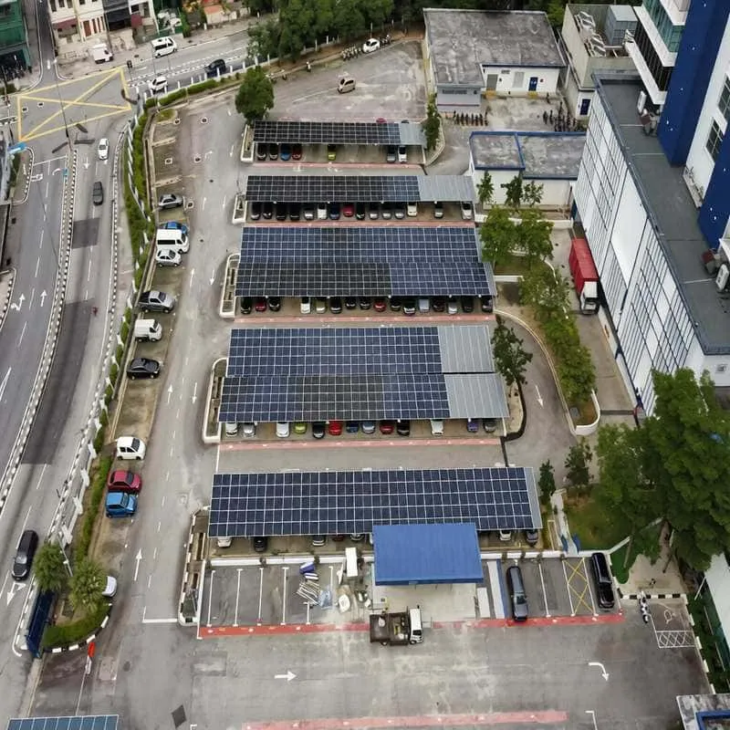
Commercial Solar Carport
Designed for commercial parking lots, office parks, schools, hospitals, shopping centers and industrial facilities requiring scalable PV canopy structures.
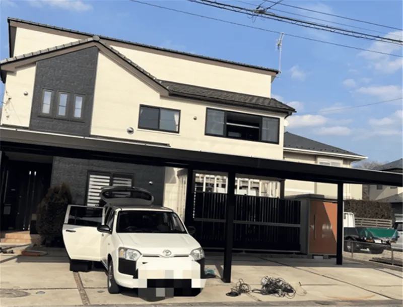
Residential Solar Carport
Suitable for residential parking spaces, villas and small distributed PV projects, with custom size, module layout and appearance options.
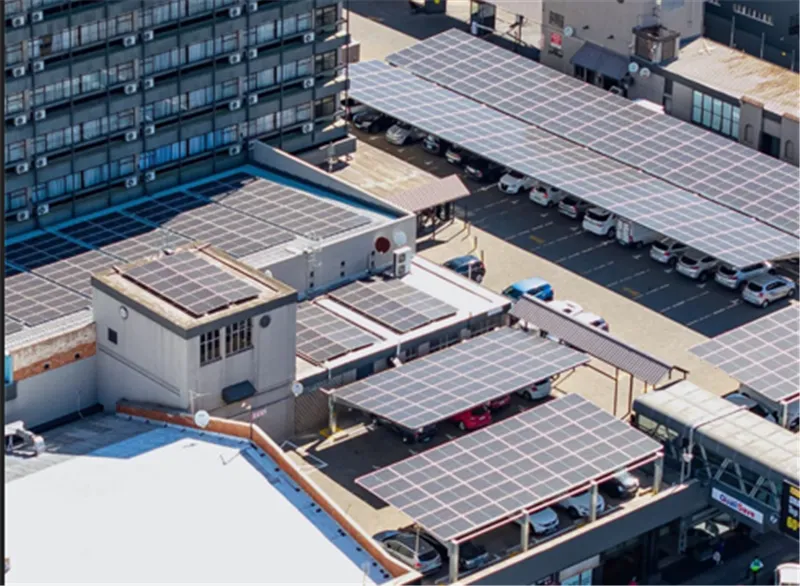
Solar Carport for EV Charging
Supports parking lot solar power generation and EV charging station integration for commercial sites, public parking areas and fleet charging projects.
Waterproof Solar Carport
Waterproof and drainage options are available for selected carport structures, helping provide shaded parking and improved rain protection.
Adjustable Design Carport Solar Mounting for Project Layouts
Adjustable design carport solar mounting should do more than provide a generic canopy. The solar carport mount should be configured around parking bay width, column position, span, clearance height, module orientation, wind load, snow load and foundation conditions.
Easy Solar can configure single-row, double-row, single cantilever, double cantilever and custom solar carport racking structures for B2B buyers who need project-specific design instead of a fixed retail kit.
- Adjustable design carport solar mounting for different parking layouts
- Custom span, clearance height, column position and foundation design
- Solar carport mount options for 16-panel, 40-panel and project-specific layouts
- Suitable for commercial parking lots, EV charging stations and residential carports
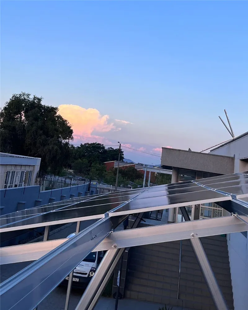
Solar Carport Layout Options for Different Parking Spaces
A solar carport mounting system should match the parking layout, vehicle clearance, span requirements and project scale. Easy Solar supports custom layout planning for single-row, double-row, cantilever and project-specific parking designs.
Single-Row Parking
Suitable for roadside parking, narrow parking areas and smaller commercial or residential solar carport projects.
Double-Row Parking
Designed for larger parking lots where two rows of parking spaces can share a central support or canopy structure.
Cantilever Structures
Single cantilever or double cantilever structures can be selected according to parking direction and space efficiency.
Custom Parking Layout
1-car, 2-car, 3-car, 4-car and project-specific layouts are available according to site drawings and customer requirements.
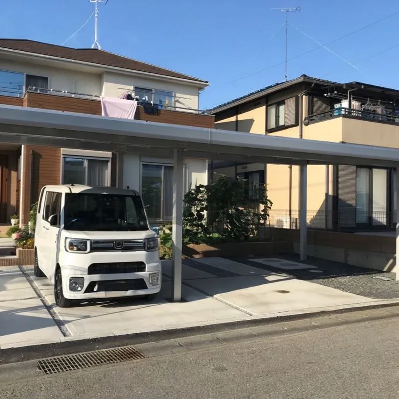
Waterproof and Drainage Options for Solar Carports
Unlike ordinary ground-mounted PV structures, solar carports are often expected to provide shaded parking and improved rain protection. Easy Solar can provide waterproof and drainage options for selected solar carport mounting system structures according to module layout and project design.
Depending on the project requirements, the carport solar mounting system can be configured with waterproof rails, drainage channels, water guide structures or PV canopy solutions to help manage rainwater flow.
- Waterproof solar carport options for selected project designs
- Drainage channels and water guide structures available
- PV canopy layout support for parking protection and power generation
- View waterproof solar carport mounting system →
Carport Frame and Structure for Solar Panels
A carport frame for solar panels means the complete load-bearing structure that forms the solar parking canopy. It is not the aluminum border around an individual PV module. The full carport structure for solar panels typically includes posts, columns, main beams, secondary beams, braces, purlins or PV rails, base plates, foundation interfaces and module fixing components.
Easy Solar can configure solar panel carport frames according to parking bay width, vehicle clearance, column position, span, module layout, waterproof requirements, local wind and snow loads and foundation conditions. The final solar panel carport structure can be adapted for single-row, double-row, cantilever, commercial, residential and EV charging projects.
- Complete load-bearing carport frame rather than the border of an individual PV module
- Custom posts, columns, beams, braces, purlins, rails and foundation interfaces
- Project-specific span, clearance height, parking layout and module arrangement
- Concrete foundation and selected ground screw solutions according to site conditions
- Structural configuration support for local wind load and snow load requirements
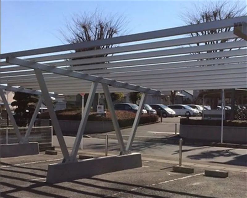
Posts & Columns
Vertical structural supports configured according to parking layout, canopy height, span and foundation design.
Main Beams
Primary load-bearing members that connect the columns and support the upper solar canopy structure.
Secondary Beams & Purlins
Secondary structural members that distribute module loads and support rails or direct module fixing.
Braces & Connections
Bracing and connection parts help improve frame stability and transfer loads between structural members.
Base Plates & Foundations
Base plates, anchors and foundation interfaces connect the solar carport structure to the ground.
PV Rails & Module Interface
Rails, purlins and clamps create the final interface between the carport frame and the PV modules.
Solar Carport Mounting and Installation Components
After the main carport frame is defined, matched PV mounting, waterproofing, fastening and grounding parts help complete the system and reduce on-site adjustment for EPC contractors, installers and distributors.
Solar Mounting Rails
PV mounting rails and profiles support module alignment, row positioning and efficient installation.
Mid & End Clamps
Module clamps secure framed PV modules to the rails or purlins of the carport structure.
Rail Connectors & Splices
Rail connectors and splice kits support longer module rows and consistent rail alignment.
Waterproof Parts
Waterproof rails, drainage channels and water guide components are available for selected canopy designs.
Fasteners & Connection Hardware
Stainless steel bolts, nuts, washers and connection hardware support reliable project assembly.
Grounding & Bonding Parts
Grounding clips, lugs and bonding components help complete the PV mounting and electrical bonding system.
Factory-Direct Solar Carport Mounting Solutions
Easy Solar supports EPC contractors, installers, distributors and project developers with solar carport mounting system factory capability, project-based customization, OEM support and export-ready delivery.
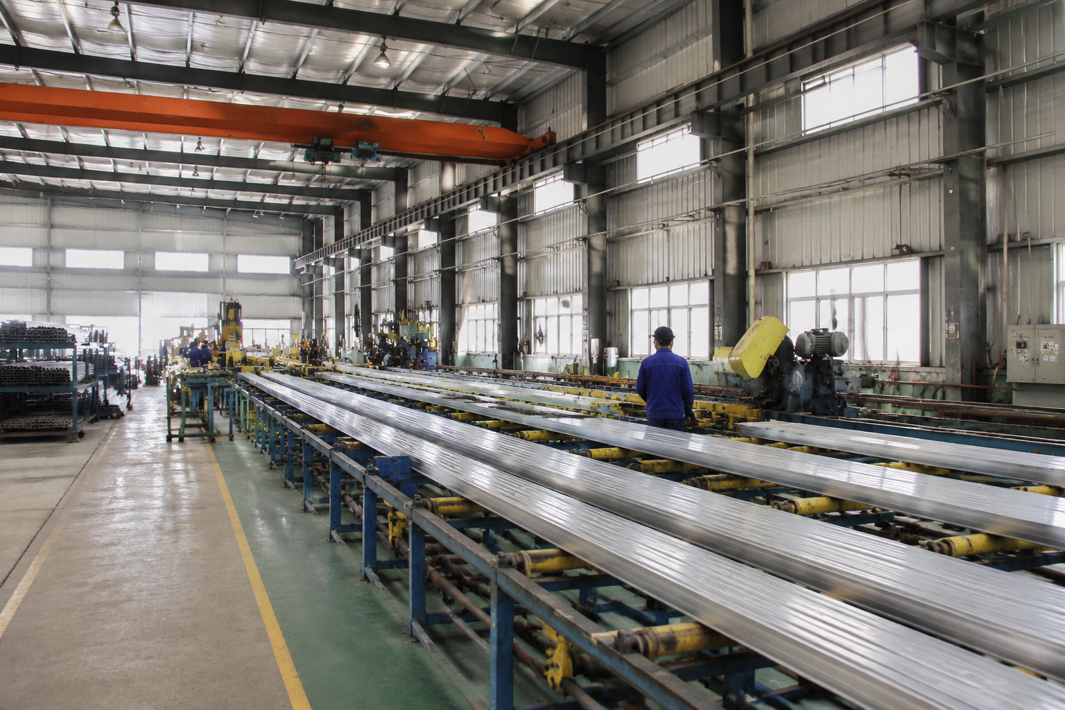
Manufacturing Control
Solar carport components can be supplied according to order quantity, structural layout, parking dimensions and OEM requirements.
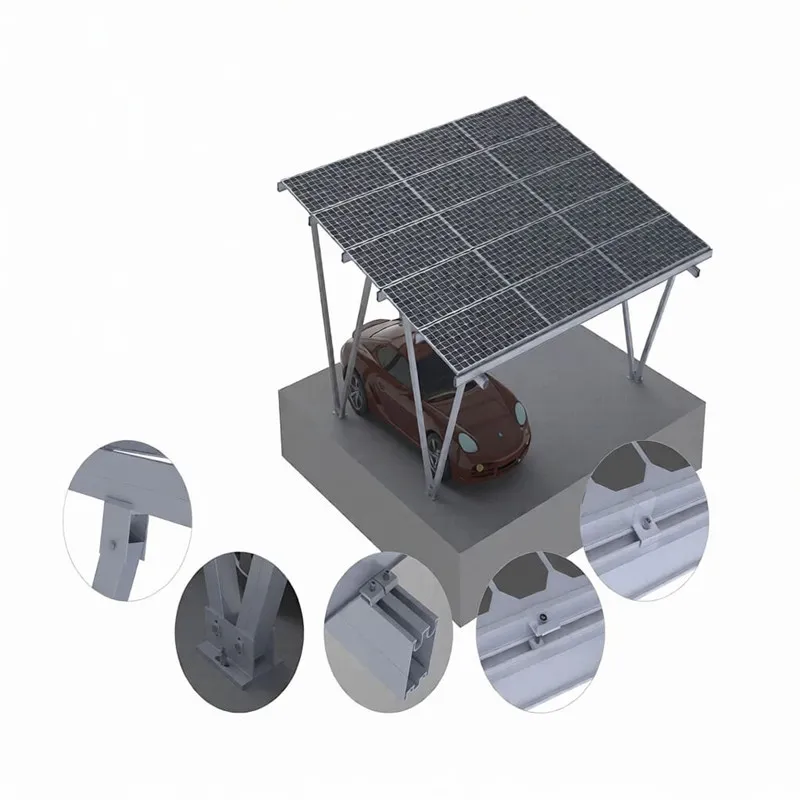
Component Consistency
Stable component quality helps reduce on-site adjustment, improve installation efficiency and support repeatable project delivery.
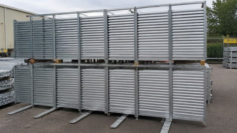
Export-Ready Supply
We support bulk orders, distributor supply, project shipments and customized packaging for international solar carport customers.
Solar Carport Mounting System Manufacturer & Supplier
Easy Solar supports B2B buyers with factory-direct solar carport racking, carport structures, OEM packaging and export-ready project supply. Project quotations can be prepared according to parking layout, module size, span, clearance height, waterproof requirements and local load conditions.
Factory-Direct Supply
Factory-direct solar carport mounting system support for project orders, distributor supply and OEM customers.
Manufacturer Customization
Custom span, clearance height, material, foundation and waterproof design based on project drawings.
Supplier Quotation
Solar carport mounting system supplier quotation based on parking spaces, module size and load requirements.
Bulk & Wholesale Orders
Bulk solar carport racking, carport frame for solar panels and complete component packages for B2B buyers.
Solar Carport Mounting System Specifications
Solar carport structures can be configured according to parking layout, project capacity, module size, span, clearance height, wind load, snow load and waterproof requirements.
| Product Name | Solar Carport Mounting System / Solar Carport Racking / Carport Frame for Solar Panels / PV Carport Canopy Systems |
|---|---|
| Application | Commercial parking lots, residential parking spaces, EV charging stations, office parks, shopping centers, schools, hospitals, industrial sites and solar parking canopy projects |
| Structure Options | Single-row carport, double-row carport, single cantilever, double cantilever, solar carport mount for 16 panels, solar carport mount for 40 panels and custom parking layouts |
| Material | Aluminum alloy profiles, stainless steel fasteners and project-specific structural components. Other structure options can be discussed according to project requirements. |
| Foundation Options | Concrete foundation and selected ground screw foundation options, depending on site condition and engineering requirements |
| Waterproof Option | Waterproof rails, drainage channels and water guide components available for selected PV canopy designs |
| Module Layout | Portrait or landscape layout, customized according to module size, parking layout and canopy design |
| Design Support | Project-based configuration support for span, clearance height, wind load, snow load, parking bay width and foundation conditions |
| Buyer Type | EPC contractors, solar installers, distributors, wholesalers, OEM customers, EV charging project developers and commercial PV project owners |
Turn Parking Areas into Solar Power Assets
Solar carports help transform parking spaces into clean energy generation assets while offering shade and improved parking protection. For commercial sites and EV charging stations, a well-designed solar carport mounting system can support both power generation and a more professional parking environment.
- Suitable for parking lot solar canopy and EV charging station projects
- Supports shaded parking, distributed PV generation and commercial site image
- Customizable structure for different parking layouts and module arrangements
- Factory-direct supply for EPC contractors, installers and distributors
- Export-ready packaging for international project delivery
Request a Solar Carport Mounting Quote
Send Easy Solar your parking layout, module size, project location, foundation preference and waterproof requirements. Our team will help you select a suitable solar carport mounting system, carport solar racking structure or PV carport canopy package and prepare a factory-direct quotation.
- Parking layout and number of parking spaces
- PV module size and module arrangement
- Span, clearance height and column position
- Waterproof or non-waterproof requirement
- Foundation type and site condition
- Wind load, snow load and project location
- Drawing, site photos or installation plan
Solar Carport Mounting System FAQ
Common questions from EPC contractors, installers, distributors, EV charging project developers and commercial PV buyers.
What is a solar carport mounting system?
A solar carport mounting system is a PV canopy structure used to install solar panels above parking spaces. It can provide shaded parking, support solar power generation and serve commercial, residential or EV charging projects.
What does carport frame for solar panels mean?
It means the complete load-bearing solar carport structure, including posts, columns, beams, braces, purlins or PV rails, base plates and foundation connections. It does not mean the aluminum frame around an individual solar panel.
What projects is a solar carport mounting system suitable for?
Easy Solar solar carport mounting system solutions are suitable for commercial parking lots, residential parking spaces, office parks, shopping centers, schools, hospitals, industrial sites and EV charging station projects.
Do you provide commercial solar carport mounting systems?
Yes. We provide commercial solar carport structures for parking lots, business parks, public parking areas and distributed PV canopy projects. The structure can be customized according to parking layout and project requirements.
Can your solar carport mounting system be used for EV charging stations?
Yes. Solar carport mounting systems can be used for EV charging station projects, helping combine parking protection, solar power generation and EV charging infrastructure.
Do you provide waterproof solar carport structures?
Waterproof and drainage options are available for selected solar carport structures. The final waterproof design depends on module layout, canopy structure and project requirements.
What parking layouts can your solar carport support?
Easy Solar can support single-row parking, double-row parking, single cantilever structures, double cantilever structures and customized parking layouts such as 1-car, 2-car, 3-car and 4-car designs.
Can the span and clearance height be customized?
Yes. Span, clearance height, column position and parking bay width can be customized according to site drawings, vehicle requirements, module arrangement and structural design requirements.
What foundation options are available for solar carports?
Common solar carport foundation options include concrete foundations and selected ground screw solutions. The final foundation type should be selected according to soil condition, structural design and local engineering requirements.
Can your solar carport structure be customized for wind and snow loads?
Yes. Solar carport structures can be configured according to local wind load, snow load, module size, span, clearance height, foundation condition and project installation environment.
What information should I provide for a quotation?
Please provide your project location, parking layout, number of parking spaces, PV module size, module layout, span, clearance height, waterproof requirement, wind load, snow load, foundation preference and any available drawings or site photos.
What is adjustable design carport solar mounting?
Adjustable design carport solar mounting means the carport structure can be configured around parking bay width, column position, span, clearance height, module layout, waterproof requirement, foundation condition, wind load and snow load.
Do you supply solar carport racking for sale?
Yes. Easy Solar supplies solar carport racking for B2B projects, including carport frames for solar panels, posts, beams, rails, clamps, waterproof parts, fasteners and grounding components.
Can you design a solar carport mount for 16 panels or 40 panels?
Yes. Solar carport mount layouts can be customized for 16 panels, 40 panels or larger project capacities according to PV module size, parking layout, span, clearance height and structural requirements.
Do you provide factory-direct solar carport mounting systems for international projects?
Yes. Easy Solar is a China solar carport mounting system manufacturer supporting project customization, supplier quotations, OEM packaging and export-ready delivery for international buyers.