
Ground Solar Mounting Systems
Fixed-tilt ground PV racking configured from module layout, terrain, geotechnical conditions, structural loads and the foundation system approved for the site. Foundation compatibility is product-specific; it should not be assumed from the ground-mount category alone.
- Fixed-Tilt Racking
- Foundation Compatibility
- Geotechnical Inputs
- Terrain & Drainage
- Project Structural Design
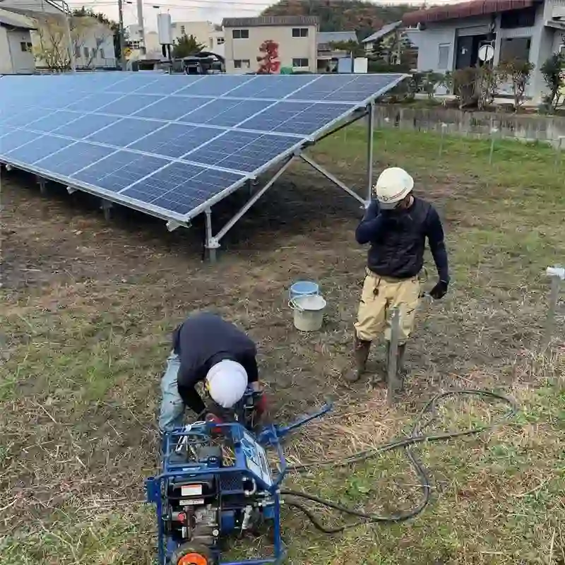
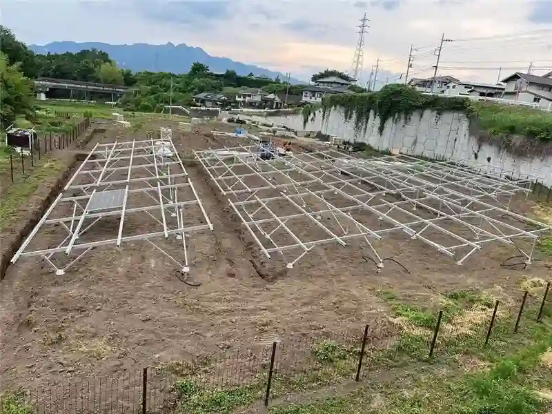
Fixed-Tilt Racking and Foundations Are Separate Design Layers
The racking defines the module table, posts, beams or purlins, bracing and connection geometry. The foundation transfers those loads into the ground. A ground-mount product family may support one or several foundation types, but each combination needs to be documented for the selected system.
- Define module orientation, modules per table, tilt, clearance and row arrangement.
- Use the selected racking system's documented post and foundation compatibility.
- Coordinate member spacing and attachment locations with the structural calculation.
- Specify materials and corrosion protection from the actual system and site exposure.
Match the Foundation to the Site and the Selected Racking System
Do not treat driven piles, ground screws, helical piles, concrete and ballast as interchangeable foundations.
Driven Piles
Used where pile driving, required embedment and verified axial/lateral performance suit the soil and racking design.
Ground Screws
Selected from screw geometry, installation method, torque or field-test data, soil conditions and the compatible post interface.
Helical Piles / Screw Piles
Related to screw foundations but not automatically the same product as a ground screw. Use the exact pile and connection data specified for the project.
Concrete / Precast
Useful where pile or screw installation is unsuitable or where the engineered design calls for concrete footings, piers or precast supports.
Confirm the Site and Array Before Finalizing the Structure
Geotechnical, terrain, module and structural information should be reviewed together rather than repeated in separate selection sections.
Geotechnical Data
Soil profile, groundwater, corrosion conditions and field tests required by the selected foundation method.
Module & Table Geometry
Module dimensions, orientation, modules per table, tilt, ground clearance and preliminary row arrangement.
Terrain & Civil Constraints
Site slope, elevation variation, grading limits, drainage, access and underground or site restrictions.
Structural Design Basis
Project location, governing standard and applicable wind, snow, seismic and other required design actions.
Verify the Complete Path from Module to Ground
Member sizes, materials and connection hardware should come from the selected system drawing and structural calculation.
Module Support
Rails or purlins and module clamps transfer loads from the module frame into the table structure.
Primary Structure
Beams, braces and posts form the fixed-tilt table and transfer forces toward the foundation.
Foundation Interface
Post-to-pile, screw or concrete connections must match the foundation and racking system actually engineered for the site.
Data to Confirm for the Final Ground-Mount System
| Racking architecture | Fixed-tilt table geometry, post arrangement, rail/purlin configuration and bracing for the selected system. |
|---|---|
| Foundation compatibility | Foundation types explicitly supported by the selected racking product and project engineering. |
| Geotechnical basis | Soil, groundwater, corrosion environment and required pull, lateral, torque or production-test data. |
| Array geometry | Module model, orientation, tilt, clearance, row spacing and table configuration. |
| Materials & corrosion | Actual steel, aluminum, coatings and fastener materials specified for the system and site exposure. |
| Project outputs | Layout, structural drawings, foundation information, BOM and installation documentation within the agreed engineering scope. |
Send the Site, Module and Foundation Information
Start with project location, module data, preliminary layout and available geotechnical information. The racking and foundation compatibility can then be reviewed against the actual site.
- Project location and design criteria
- PV module datasheet and preliminary layout
- Terrain / topographic information
- Geotechnical report or field-test data if available
- Preferred foundation type, if already defined
Ground-Mount Selection Questions
Is a ground screw the same as a helical pile?
No. They are related screw-type foundation concepts, but geometry, installation method, connection details and design data can differ. Use the exact foundation specified for the selected system.
Can one fixed-tilt rack use every foundation type?
No. Some product families support several foundation options, while others are designed around specific piles, screws or concrete interfaces. Verify compatibility from the selected system documentation.
What information is needed for a ground-mount quotation?
Send project location, module data/layout, terrain information, design criteria and any available geotechnical or foundation information.