
Solar Mounting Clamps
Easy Solar supplies solar mounting clamps for framed PV modules, including solar panel mid clamps, end clamps, adjustable clamp sets and rail fixing clamp components. Clamp height, rail interface, bolt size, finish and packaging can be matched for roof, ground, carport and selected balcony mounting systems.
- Mid & End Clamps
- Frame Height Matching
- Rail Channel Compatibility
- Black & Mill Finish Options
- OEM & Bulk Supply
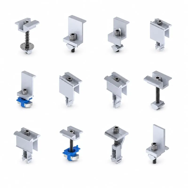
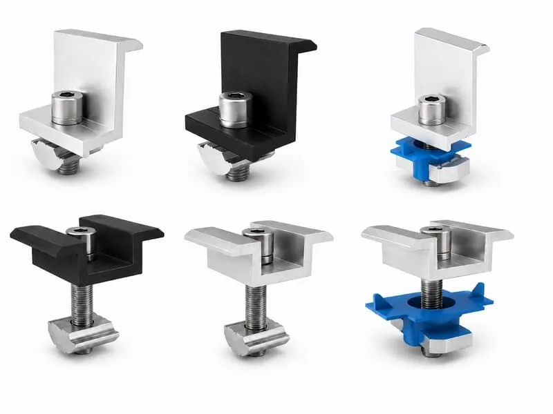
Solar Panel Clamps for Framed PV Modules
Solar panel clamps secure framed modules to compatible rails, purlins or module-support profiles. Mid clamps are positioned between adjacent modules, while end clamps secure the outer edges of a module row.
The correct clamp must match the PV module frame height, rail channel, bolt or channel nut, clamp position and installation method. Easy Solar can supply standard solar mounting clamps or discuss custom clamp bodies, bolt lengths, finishes and pre-assembled project sets.
- Solar mounting clamps for roof, ground, carport and selected balcony systems
- Mid clamps for adjacent module edges and end clamps for array perimeters
- Fixed-height and adjustable clamp configurations
- Rail, bolt, channel nut and grounding-component compatibility support
Solar Mounting Clamp Types
Select the clamp according to its position in the module row, frame height, rail profile, finish and required installation method.
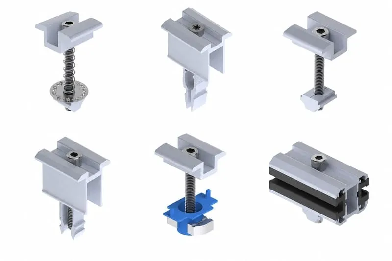
Solar Panel Mid Clamps
Mid clamps secure the adjacent inner edges of two framed PV modules and maintain the required installation gap between modules.
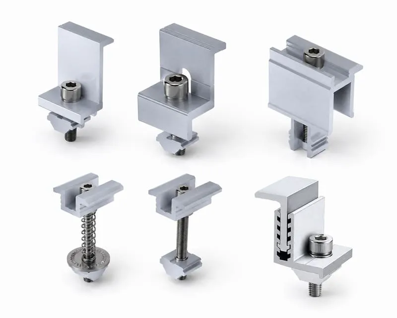
Solar Panel End Clamps
End clamps secure the outside module edges at the beginning and end of a rail row and should match the module frame height.
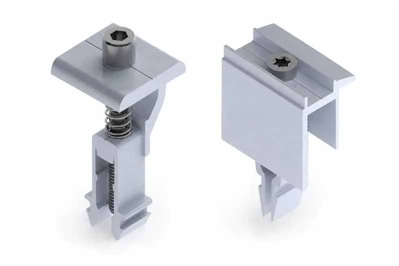
Universal and Adjustable Clamps
Adjustable clamp sets can support a defined range of framed module heights, subject to the clamp design, rail system and technical confirmation.
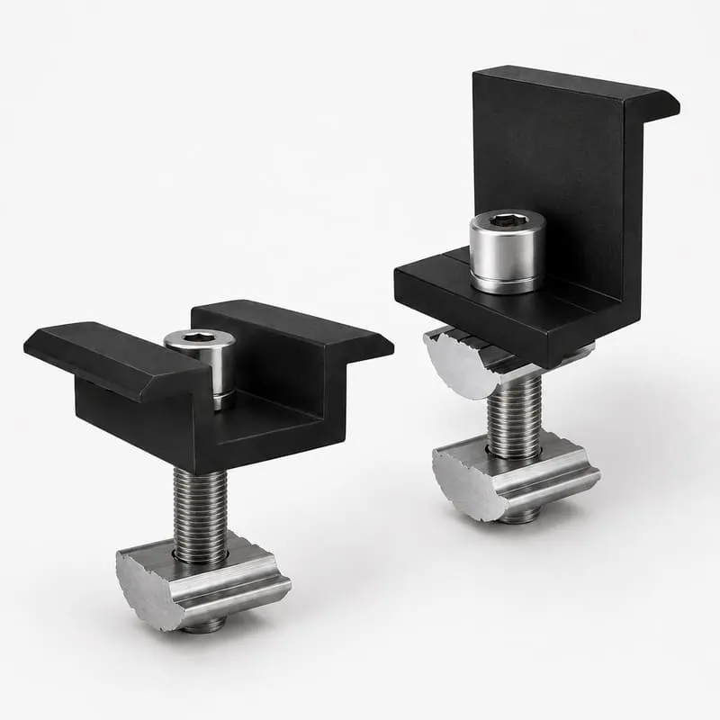
Black Solar Panel Clamps
Black-finish mid and end clamps can be matched with black module frames and selected dark rail systems for a consistent appearance.
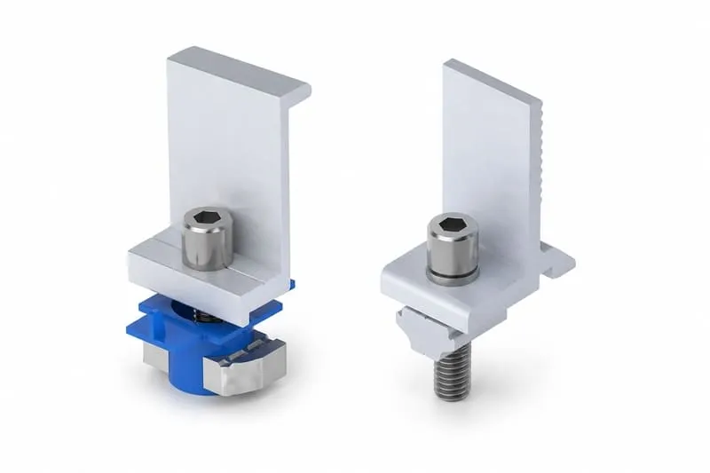
Solar Mounting Rail Fixing Clamps
Clamp assemblies can include a clamp body, bolt and compatible rail nut or channel connection for top-down module installation.
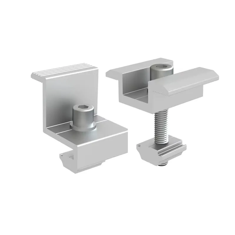
Custom Solar Mounting Clamps
Custom clamp dimensions, gripping surfaces, bolt lengths, rail interfaces, finishes, labels and packaging can be discussed from drawings or samples.
Solar Panel Mid Clamps and End Clamps
Both clamp types secure PV modules, but they occupy different positions and must be counted differently in the project bill of materials.
| Comparison | Mid Clamp | End Clamp |
|---|---|---|
| Installation Position | Installed between two adjacent framed PV modules | Installed at the outside edge of the first and last modules in a row |
| Module Contact | Engages the edges of two neighboring modules | Engages one outside module edge |
| Frame Height | Must work within the defined module frame-height range of the clamp design | Often selected or adjusted according to the module frame height |
| Rail Interface | Requires a compatible rail channel, bolt and nut or click-in interface | Requires a compatible rail channel, bolt and nut or end-clamp interface |
| Project Quantity | Calculated from module rows and joints between modules | Calculated from the exposed ends of each module row |
Module Frame Height and Rail Compatibility
Clamp selection begins with the PV module frame and the rail profile. A clamp that is too high, too low or incompatible with the rail channel may not seat correctly or provide the intended installation interface.
Provide the module datasheet, frame height, rail cross-section, bolt or channel-nut details and clamp position. Universal claims should still be checked against the actual rail and module system before ordering.
- PV module frame height, frame shape and clamping surface
- Rail top channel, slot width, nut type and bolt size
- Fixed-height or adjustable clamp working range
- Required inter-module gap and clamp-body width
- Portrait or landscape layout and approved module clamping zones
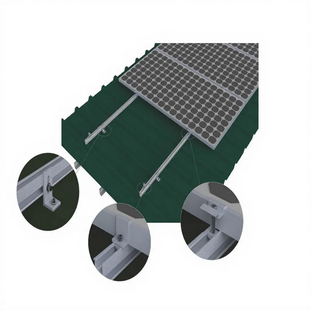
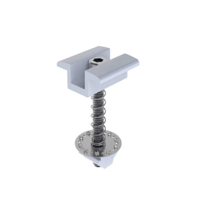
Module Clamps, Roof Clamps and Mounting Brackets
This page focuses on module clamps that secure framed PV panels to mounting rails or supporting profiles. It does not treat every product containing the word clamp as the same accessory.
Standing-seam clamps attach a mounting system to a metal roof seam. Mounting brackets connect rails or structures to other surfaces. Cable clips manage PV wiring. Keeping these categories separate helps buyers select the correct component and prevents incompatible substitutions.
- Module clamp: secures the PV module frame to a rail or support profile
- Standing-seam clamp: attaches the mounting system to a metal roof seam
- Mounting bracket: connects rails, attachments or structural members
- Cable clip: secures and organizes PV cables
Solar Panel Mounting Clamps for PV Systems
Module clamps can be used across different mounting systems when the module frame, rail profile, support interface and installation requirements are compatible.
Roof Solar Mounting
Mid and end clamps for rail-based tile, metal and selected flat-roof mounting systems.
View Roof Systems →Ground Solar Mounting
Module clamps matched to compatible ground-mount rails, purlins and module layouts.
View Ground Systems →Solar Carport Systems
Clamps for framed modules installed on standard or selected waterproof carport rail interfaces.
View Carport Systems →Balcony Solar Mounting
Compact clamp options for selected balcony rails, brackets and framed-module systems.
View Balcony Systems →Aluminum Solar Panel Clamps and Fastener Options
Solar mounting clamp assemblies commonly combine an aluminum clamp body with compatible bolts, nuts or channel components. The exact materials and surface finish should follow the confirmed product design and installation environment.
Mill-finish and black-finish clamp options can be discussed, together with stainless steel or project-specific fasteners. Finish selection should consider the rail system, module-frame appearance, corrosion environment and buyer specification.
- Aluminum clamp bodies for framed PV module mounting
- Mill, anodized black or project-specific finish options
- Compatible stainless steel bolts and rail-channel hardware
- Pre-assembled or component-packed clamp sets
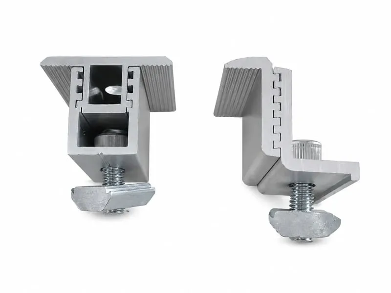
Components Used with Solar Mounting Clamps
Clamps should be selected together with rails, fasteners, grounding parts and the complete mounting system rather than purchased as isolated components.
Solar Mounting Rails
Rail channels and profiles matched to the clamp body, bolt and channel nut.
View Mounting Rails →Bolts & Fasteners
Bolts, nuts and washers selected according to clamp height, thread and rail interface.
View Fasteners →Grounding Parts
Grounding clips and bonding components selected for the module, clamp and rail system.
View Grounding Parts →Mounting Brackets
Connection brackets supporting the rails or structures used below the module clamps.
View Mounting Brackets →Rail Splice Kits
Connectors joining compatible rail sections across longer module rows.
View Rail Splices →Solar Mounting Kits
Project packages combining rails, clamps, fasteners and selected mounting accessories.
View Mounting Kits →How to Select Solar Mounting Clamps
Confirm the module, rail and installation details together before finalizing clamp size, bolt length, finish and project quantity.
Check the Module Frame
Provide frame height, profile shape, module dimensions and approved clamping zones.
Confirm the Rail Channel
Provide rail cross-section, slot dimensions, nut type and bolt interface.
Select Clamp Type
Confirm mid, end, adjustable, black-finish or project-specific clamp requirements.
Prepare the BOM
Confirm module layout, row count, clamp quantity, packaging and delivery plan.

Custom Solar Mounting Clamp Manufacturing
Easy Solar supports standard clamp supply and drawing-based projects for distributors, EPC contractors, installers and OEM buyers. Custom work can be discussed for clamp bodies, bolt lengths, rail interfaces, finishes and packaging.
Production may include aluminum profile processing, cutting, machining, drilling, surface treatment, bolt and channel-nut matching, pre-assembly and project labeling. Final feasibility depends on the drawing, material, process and order quantity.
- Custom clamp height, width, gripping surface and rail interface
- Custom bolt length, thread, nut type and pre-assembly option
- Mill, black or project-specific surface finish
- Drawing review, sample matching and compatibility confirmation
- Bulk cartons, project sets, labels and OEM packaging
Solar Mounting Clamp Manufacturer and Supplier
Easy Solar supports professional buyers with clamp processing, fastener matching, pre-assembly, inspection and export-ready project supply.

Clamp Body Processing
Clamp bodies can be processed according to confirmed dimensions, gripping surfaces, holes, finishes and rail interfaces.
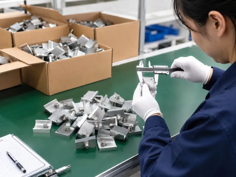
Fastener Matching & Assembly
Bolts, nuts and rail-channel parts can be matched and supplied as loose components or pre-assembled clamp sets.
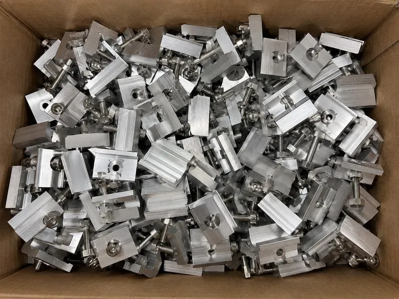
Bulk & Project Packaging
Mid clamps, end clamps and fasteners can be packed by model, project set, carton quantity or OEM label requirements.
Solar Mounting Clamps Specifications
Final specifications depend on module frame height, rail profile, clamp type, bolt interface, finish and project installation requirements.
| Product Name | Solar Mounting Clamps / Solar Panel Clamps / PV Module Mid Clamps and End Clamps |
|---|---|
| Clamp Types | Mid clamps, end clamps, universal or adjustable clamps, black clamps, rail fixing clamp assemblies and custom clamp sets |
| Module Type | Framed PV modules, subject to confirmed frame height, frame shape and clamping requirements |
| Applications | Roof, ground, carport and selected balcony solar mounting systems with compatible rails or support profiles |
| Clamp Body Material | Aluminum alloy or project-specific material according to the product design and buyer specification |
| Fastener Options | Compatible bolts, nuts, washers and channel hardware according to rail slot and clamp height |
| Finish Options | Mill finish, black finish or project-specific surface treatment available upon discussion |
| Frame Height | Fixed or adjustable working range selected according to the PV module frame and clamp design |
| Rail Compatibility | Matched according to rail top channel, slot dimensions, channel nut, bolt type and installation system |
| Customization | Clamp dimensions, gripping surface, bolt length, finish, pre-assembly, labels and packaging available upon discussion |
| Buyer Type | EPC contractors, solar installers, distributors, wholesalers, OEM customers and PV project developers |
Request a Solar Mounting Clamp Quote
Send Easy Solar the module datasheet, frame height, rail profile, clamp type, bolt details, required finish and project quantity. Our team will help review compatibility and prepare a factory-direct quotation.
- Mid clamp, end clamp or adjustable clamp
- PV module datasheet and frame height
- Rail cross-section and channel dimensions
- Bolt size, length, thread and nut type
- Clamp finish and color requirement
- Module layout and estimated clamp quantity
- Packaging, label and delivery requirements
Solar Mounting Clamps FAQ
Common questions from solar installers, EPC contractors, distributors and PV mounting accessory buyers.
What are solar mounting clamps?
Solar mounting clamps are components used to secure framed PV modules to compatible mounting rails, purlins or support profiles. The main categories are mid clamps and end clamps.
What is the difference between a solar panel mid clamp and end clamp?
A mid clamp is installed between two adjacent modules, while an end clamp secures the outside edge of the first or last module in a row.
How do I choose the correct clamp height?
Clamp height must match the PV module frame height and the clamp design. Please provide the module datasheet, frame profile and clamp position before ordering.
Are solar panel clamps compatible with all mounting rails?
No single clamp should be assumed to fit every rail. Compatibility depends on the rail channel, slot dimensions, nut type, bolt interface and clamp body.
Do you provide adjustable or universal solar mounting clamps?
Adjustable clamp options can be discussed for a defined range of framed module heights. The final working range depends on the clamp and rail design.
Do you provide black solar panel clamps?
Yes. Black-finish clamp options can be discussed together with matching module frames, rail systems, bolts and order quantities.
Are module clamps the same as standing-seam roof clamps?
No. Module clamps secure PV module frames to rails or supports. Standing-seam clamps attach the mounting system to the seam of a compatible metal roof.
Can clamps include bolts and rail channel nuts?
Yes. Clamp bodies can be supplied with compatible bolts, nuts and rail-channel hardware as loose parts or pre-assembled sets.
Can you manufacture custom solar mounting clamps?
Yes. Custom clamp dimensions, gripping surfaces, bolt lengths, rail interfaces, finishes, pre-assembly and packaging can be discussed from drawings or samples.
What information is needed for a quotation?
Please provide the clamp type, module datasheet, frame height, rail profile, bolt and nut details, finish, module layout, quantity and packaging requirements.