
Solar Roof Hooks
Easy Solar supplies solar roof hooks for tile hook solar mounting systems, including fixed, adjustable and project-specific stainless steel roof hook options. Hook height, base plate, arm position, rail connection, holes, fasteners and packaging can be matched for tile roof PV projects, installers, EPC contractors, distributors and OEM buyers.
- Fixed & Adjustable Hooks
- Tile Roof Applications
- Rail Connection Hardware
- Custom Base Plates & Arms
- OEM & Bulk Supply
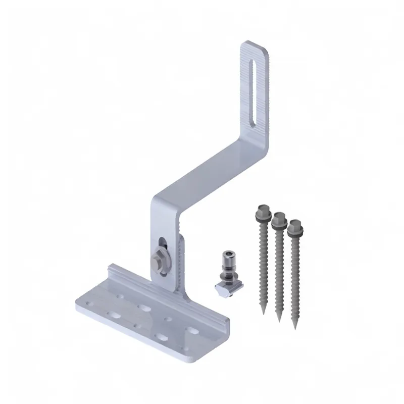
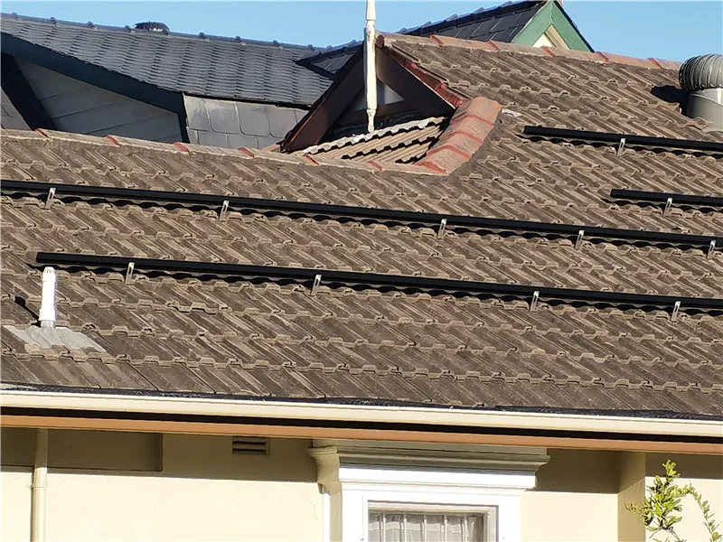
Tile Hook Solar Mounting for Rail-Based PV Systems
Tile hook solar mounting uses a roof hook to transfer loads from the solar mounting rail to a suitable roof structure below the tile covering. The hook arm passes through the tile overlap or prepared tile interface and connects to the rail above the roof surface.
The correct hook must match the roof tile shape, batten or rafter position, tile clearance, base plate, fixing holes, rail profile and installation layout. Easy Solar can supply standard roof hooks or discuss custom arm height, base plate dimensions, slot positions, fasteners and project packaging.
- Solar roof hooks for selected tile roof PV mounting systems
- Fixed, height-adjustable and multi-position hook options
- Compatible connection with aluminum solar mounting rails
- Custom base plate, arm, slots, holes, material and packaging
Solar Roof Hook Types for Tile Roofs
Select the hook type according to tile profile, supporting structure, clearance, rail position and required adjustment range.
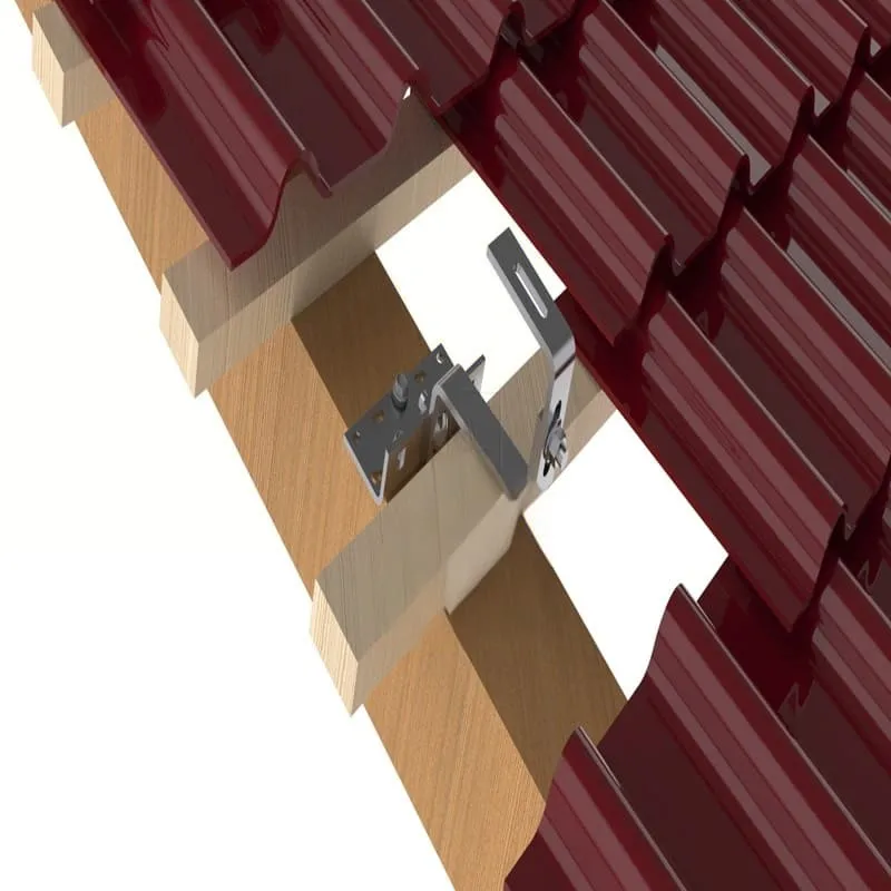
Fixed Solar Roof Hooks
Fixed hooks with a defined base plate, arm height and rail connection for compatible tile and supporting-structure conditions.
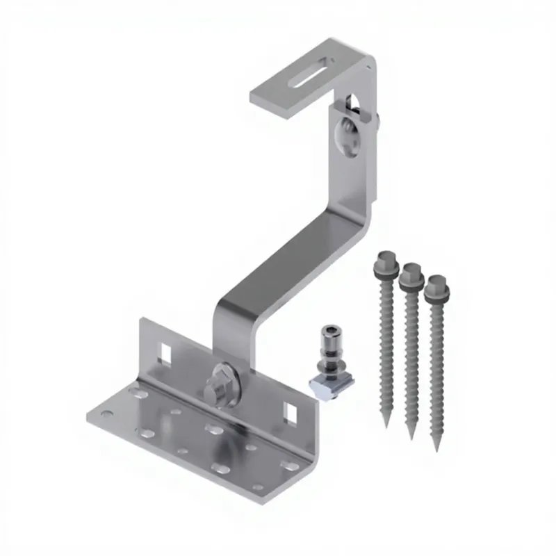
Adjustable Solar Roof Hooks
Slotted or multi-part roof hooks can provide a defined adjustment range for rail height, arm position or tile clearance.
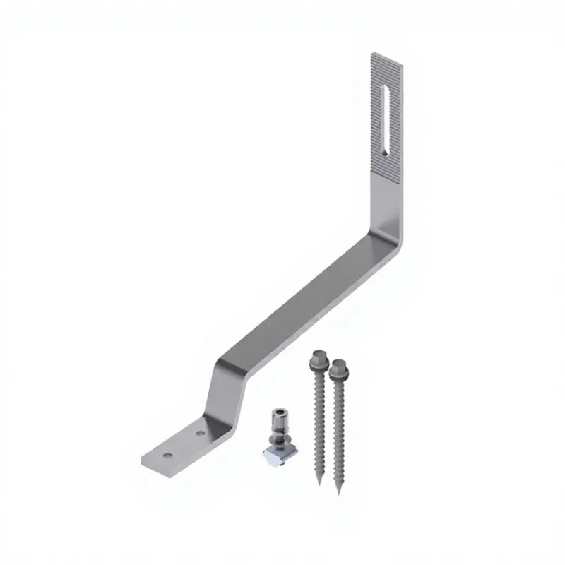
Side-Mount Roof Hooks
Roof hook designs with side rail connection or side-adjustment slots for compatible rail systems and project layouts.
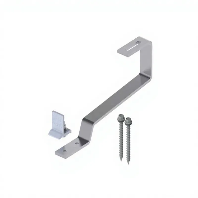
Flat Tile Roof Hooks
Low-profile hook options for selected flat tile conditions where arm geometry and tile clearance are confirmed from site information.
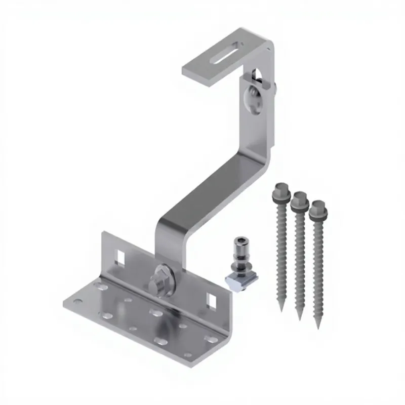
Reinforced Roof Hook Options
Wider base plates, thicker arms or project-specific hook geometry can be discussed according to the confirmed mounting design.
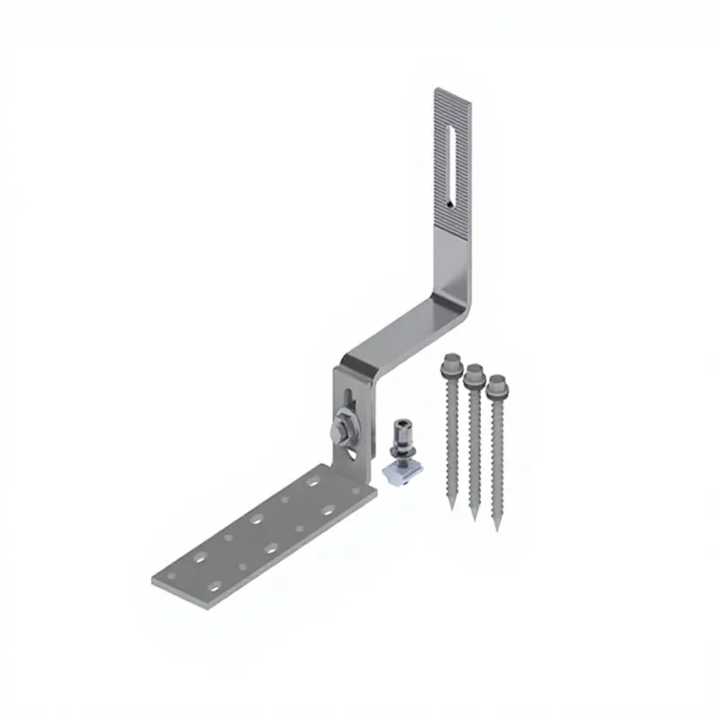
Custom Solar Roof Hooks
Drawing-based base plate, hook arm, slot, hole, bend, material, finish, fastener and packaging options for OEM and project supply.
Solar Roof Hooks vs Tile Roof Mounting Brackets
A solar roof hook is a shaped attachment that reaches from the roof structure below the tile to the mounting rail above the tile. A broader tile roof mounting bracket may describe other plates, supports or connection hardware used in the complete system.
This page focuses on roof hooks. General solar panel mounting brackets, module clamps, L feet and hanger bolts are covered on their dedicated pages so buyers can compare the correct attachment type.
- Roof hook: connects the tile roof structure to the solar mounting rail
- Mounting bracket: general connection or support component
- Module clamp: secures the PV module frame to the rail
- L foot and hanger bolt: mainly used for selected metal or penetrated roof attachments
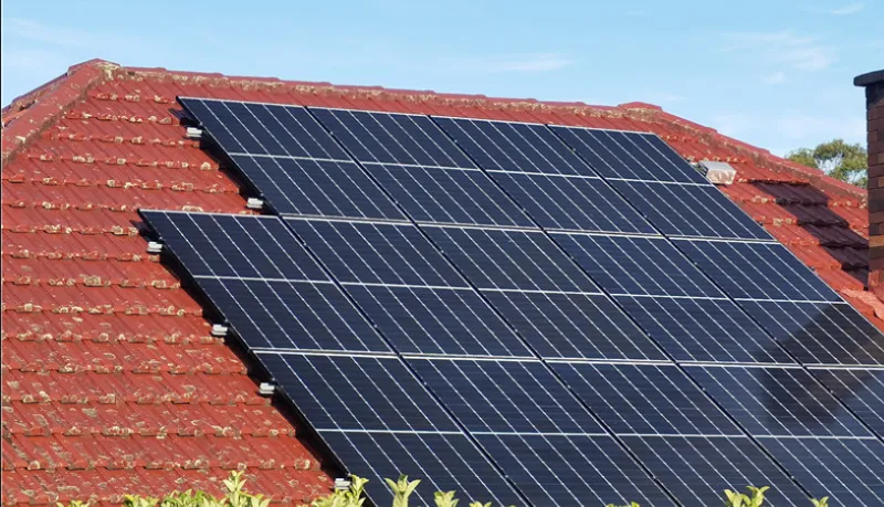
Roof Hook Selection for Different Tile Profiles
Tile shape, overlap, thickness, batten height and rafter position affect the required hook geometry and installation clearance.
Curved Tile Profiles
Hook-arm height and lateral position selected to pass through the tile overlap without unwanted contact.
Flat Tile Profiles
Low-profile or project-specific hook geometry based on tile thickness and available clearance.
Interlocking Tile Profiles
Base plate and arm position matched to the tile lock, batten and supporting member layout.
Project-Specific Roof Tiles
Hook review based on tile samples, profile dimensions, site photos and roof-structure information.
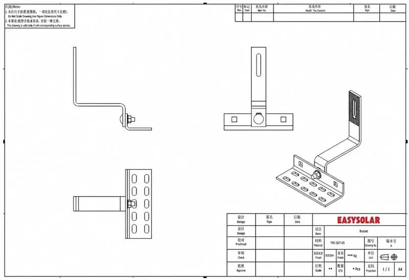
Base Plate, Hook Arm and Rail Slot Dimensions
Roof hook compatibility depends on more than the overall height. The base plate must align with the approved supporting member, the arm must clear the tile, and the upper slot must match the rail connection hardware.
Provide the base plate length and width, hole pattern, arm offset, arm thickness, hook height, adjustment range, rail slot and fastener details. Tile and roof-structure drawings help reduce uncertainty before quotation.
- Base plate length, width, thickness and fixing-hole pattern
- Hook-arm height, horizontal offset and tile clearance
- Fixed or adjustable connection positions
- Upper rail slot, bolt size and washer interface
- Left, right, centered or mirrored arm configurations where required
Fixing Solar Roof Hooks to Rafters or Supporting Members
Roof hooks must be fixed to an approved load-bearing roof member or attachment point according to the project design. Roof tiles and battens alone should not be assumed to provide the required structural fixing.
The fixing method depends on the supporting material, screw type, embedment, base plate and roof build-up. The responsible installer or project designer should confirm the roof condition, attachment location and installation procedure.
- Supporting member location and dimensions confirmed before installation
- Base plate placed on a stable and approved fixing surface
- Fastener type and embedment selected for the supporting material
- Hook arm positioned without unwanted tile loading
- Roof and tile condition checked after hook installation
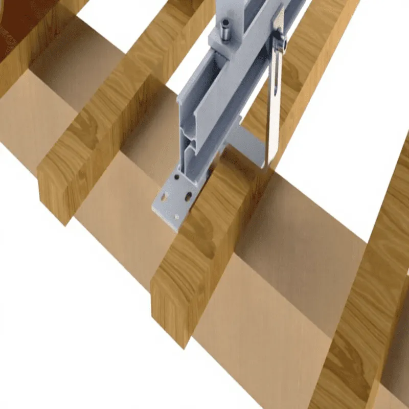
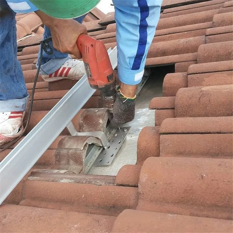
Connecting Tile Roof Hooks to Solar Mounting Rails
The upper roof-hook slot connects to a compatible solar mounting rail with a bolt, T-bolt, channel nut or other approved rail hardware. The rail connection must match the hook slot, rail profile, bolt size and required adjustment range.
Rail height and alignment may be adjusted within the defined hook and slot range. Provide the rail cross-section and hook drawing so the complete interface can be reviewed together.
- Rail profile and channel dimensions matched to connection hardware
- Bolt diameter, length, thread and washer confirmed
- Hook slot and rail position aligned within the approved adjustment range
- Roof-hook spacing coordinated with rail span and project layout
- Compatible rail splice, clamp and grounding components selected as a system
Stainless Steel Solar Roof Hook Options
Solar roof hooks are commonly produced from stainless steel or another project-specified metal selected according to hook geometry, roof environment and buyer requirements. Connection hardware may combine stainless steel fasteners with aluminum mounting rails.
Material grade, thickness, forming method, surface finish and fastener specification should be confirmed from the product drawing. Project-specific coated or alternative material options can be discussed where required.
- Stainless steel roof-hook body and compatible fastener options
- Material thickness selected according to the confirmed hook design
- Forming, bending, welding or assembly according to product structure
- Surface and corrosion requirements confirmed for the roof environment
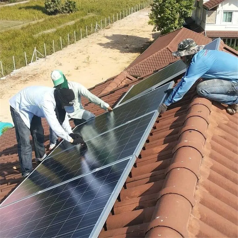
Components Used with Solar Roof Hooks
Roof hooks should be selected together with rails, fasteners, module clamps, flashing or replacement tile parts and the complete tile roof mounting system.
Solar Mounting Rails
Aluminum rail profiles matched to the upper roof-hook slot and connection hardware.
View Mounting Rails →Bolts & Fasteners
Structural screws, rail bolts, nuts and washers selected for the roof and rail interfaces.
View Bolts & Fasteners →Solar Panel Clamps
Mid and end clamps securing framed PV modules to the roof-hook-supported rail system.
View Solar Panel Clamps →Mounting Brackets
General connection and support brackets for project-specific roof and rail interfaces.
View Mounting Brackets →Flashing & Roof Interface Parts
Selected flashing, replacement tile or roof-interface components for suitable applications.
View Flashing Plates →Grounding Parts
Grounding and bonding components selected for the module, clamp and aluminum rail system.
View Grounding Parts →Solar Roof Hooks in Tile Roof PV Systems
The hook is one attachment within the complete tile roof mounting system and must be coordinated with the roof structure, rails, clamps and module layout.
Tile Roof Solar Mounting
Complete rail-based systems using compatible roof hooks, rails, clamps and fasteners.
View Tile Roof Systems →Pitched Tile Roof Projects
Hook and rail interfaces configured for pitched roof layouts and project attachment requirements.
View Pitched Tile Roof Mounting →Roof Mounting Collection
Compare tile, metal, standing-seam and flat-roof solar mounting system options.
View Roof Mounting Systems →Solar Mounting Accessories
Find rails, brackets, clamps, fasteners, grounding parts and other PV mounting hardware.
View Mounting Accessories →How to Select Solar Roof Hooks
Confirm the tile, roof structure, hook dimensions and rail interface together before choosing the hook model and project quantity.
Identify the Tile
Provide tile profile, thickness, overlap, batten height and clear photos or samples.
Confirm the Roof Structure
Identify the rafter or supporting member, fixing surface, dimensions and spacing.
Match Hook and Rail
Provide base plate, arm height, rail profile, slot, bolt and adjustment requirements.
Prepare the Project Set
Confirm hook spacing, rail rows, fasteners, quantity, packaging and delivery plan.
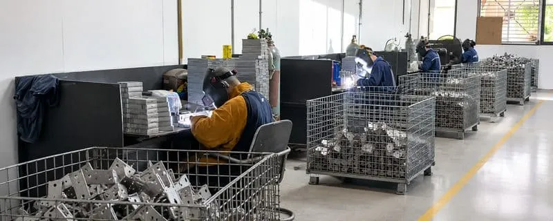
Custom Solar Roof Hook Manufacturing
Easy Solar supports standard roof-hook supply and drawing-based projects for installers, distributors, EPC contractors and OEM buyers. Custom work can be discussed for base plates, hook arms, adjustment parts, rail slots, fasteners and packaging.
Production may include cutting, bending, stamping, drilling, welding or assembly where applicable, surface treatment, dimensional inspection, fastener matching and project labeling. Final feasibility depends on the drawing, material, process and order quantity.
- Custom base plate dimensions, thickness, holes and slot positions
- Custom arm height, offset, bend shape and adjustment range
- Stainless steel or project-specific material options
- Compatible rail bolts, structural screws and washers
- Bulk cartons, project sets, OEM labels and export packaging
Solar Roof Hook Manufacturer and Supplier
Easy Solar supports professional buyers with roof-hook forming, machining, assembly, inspection and export-ready project supply.
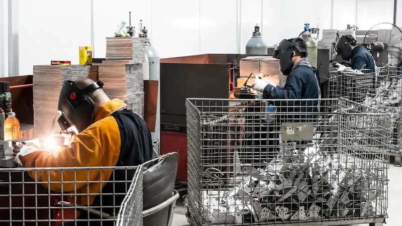
Forming & Processing
Roof-hook base plates and arms can be processed according to confirmed dimensions, bends, holes, slots and assembly requirements.
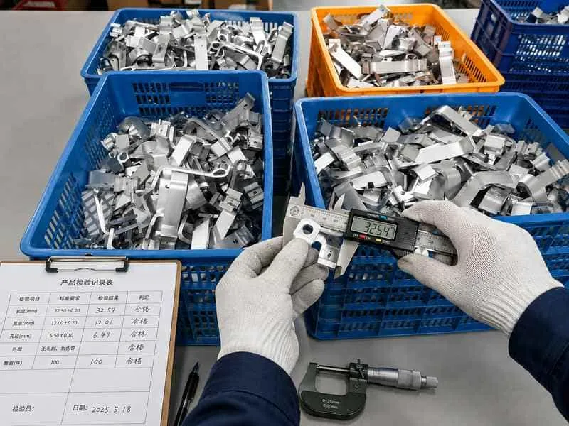
Dimension & Interface Inspection
Base plate, hook height, arm offset, holes, slots, adjustment parts and rail interfaces can be checked against the confirmed specification.
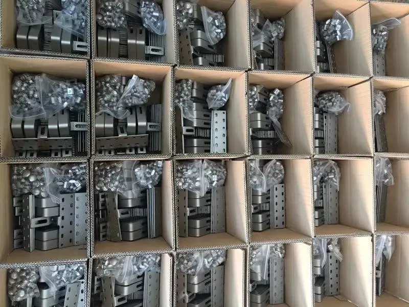
Bulk & Project Packaging
Roof hooks and compatible hardware can be packed by model, roof area, project set, carton quantity or OEM labeling requirement.
Solar Roof Hooks Specifications
Final specifications depend on tile profile, roof structure, hook geometry, rail interface, fasteners and project installation requirements.
| Product Name | Solar Roof Hooks / Tile Roof Solar Hooks / Tile Hook Solar Mounting Hardware |
|---|---|
| Hook Types | Fixed roof hooks, adjustable roof hooks, side-mount hooks, flat-tile hooks, reinforced hooks and custom hook assemblies |
| Applications | Selected curved, flat and interlocking tile roof PV mounting systems, subject to project confirmation |
| Material Options | Stainless steel or project-specific metal according to the hook design and buyer specification |
| Base Plate | Standard or customized plate dimensions, thickness, fixing holes and slot positions |
| Hook Arm | Fixed or adjustable height, horizontal offset, bend geometry and tile clearance according to roof conditions |
| Rail Compatibility | Matched according to rail profile, hook slot, T-bolt or channel-nut interface and installation layout |
| Fastener Options | Compatible structural screws, rail bolts, nuts and washers according to the roof and rail interfaces |
| Customization | Base plate, hook arm, dimensions, holes, slots, adjustment parts, material, fasteners, labels and packaging available upon discussion |
| Buyer Type | EPC contractors, solar installers, distributors, wholesalers, OEM customers and PV project developers |
Request a Solar Roof Hook Quote
Send Easy Solar the tile profile, roof-structure information, hook drawing, rail profile, fastener requirements and project quantity. Our team will help review the hook and rail interface and prepare a factory-direct quotation.
- Tile profile drawing, dimensions or sample photo
- Rafter or supporting-member information
- Base plate, arm height and adjustment requirements
- Rail cross-section and connection hardware
- Structural screw and bolt requirements
- Hook spacing and project quantity
- Packaging, labels and delivery plan
Solar Roof Hooks FAQ
Common questions from solar installers, EPC contractors, distributors and tile roof mounting buyers.
What is a solar roof hook?
A solar roof hook is a shaped attachment that connects a suitable roof structure below the tile to an aluminum solar mounting rail above the tile covering.
What does tile hook solar mounting mean?
Tile hook solar mounting means using roof hooks as the structural connection between a tile roof support and the rail-based PV mounting system.
What types of solar roof hooks do you supply?
Easy Solar can discuss fixed, adjustable, side-mount, low-profile, reinforced and drawing-based custom roof hooks for selected tile roof applications.
How do I know whether a roof hook fits my roof tile?
Please provide the tile profile, thickness, overlap, batten height, roof-structure position and clear photos or samples. Hook geometry should be checked against the actual tile and roof structure.
Are adjustable solar roof hooks available?
Yes. Adjustable hook options can provide a defined range for rail height, arm position or tile clearance. The final range depends on the hook design.
Should solar roof hooks be fixed to roof tiles?
Roof hooks should connect to an approved load-bearing supporting member or attachment point according to the project design. The tile covering alone should not be assumed to provide the structural fixing.
Are roof hooks compatible with different solar mounting rails?
Compatibility depends on the hook slot, rail profile, bolt or channel nut, washer and adjustment range. Please provide the rail cross-section for matching.
Are solar roof hooks the same as mounting brackets?
A roof hook is a specific tile roof attachment. Mounting bracket is a broader term that may include angle brackets, plates, supports and other connection components.
Can you manufacture custom solar roof hooks?
Yes. Custom base plates, hook arms, heights, offsets, holes, slots, adjustment parts, material, fasteners and packaging can be discussed from drawings or samples.
What information is needed for a quotation?
Please provide the tile profile, roof structure, hook drawing or sample, base plate and arm dimensions, rail profile, fasteners, quantity, packaging and project location.