
Solar Panel Clamps
Module clamps secure framed PV modules to a compatible rail or support profile. Select the clamp by its function, module-frame range, approved clamping zone, rail interface and installation hardware—not by appearance or nominal height alone.
- Mid Clamps
- End Clamps
- Combined / Adjustable Options
- Frame-Range Matching
- Rail-System Compatibility
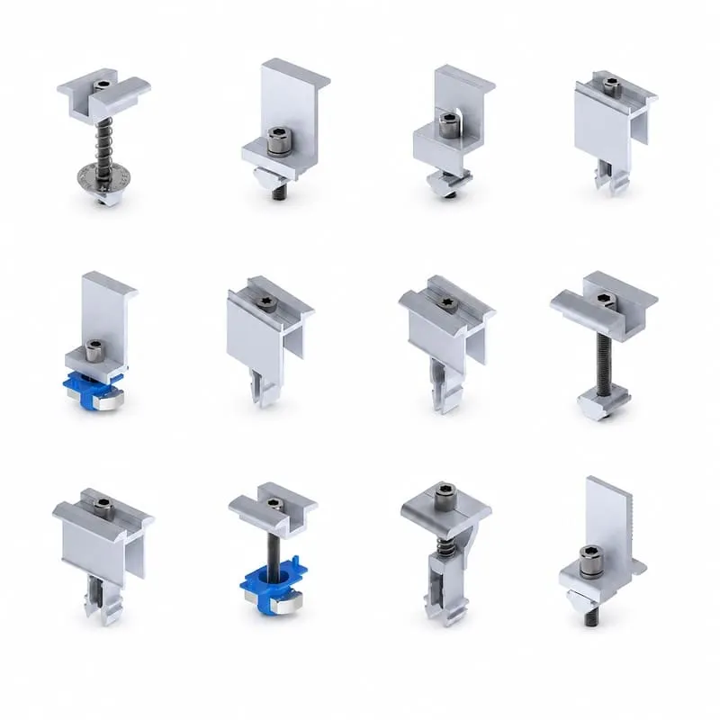
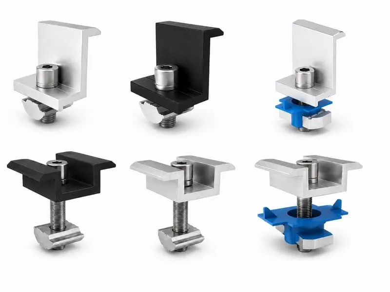
Module Clamps Secure the Panel to the Racking
A module clamp fixes the framed PV module to the mounting rail or another approved support profile. Mid clamps work between modules, while end clamps secure exposed module edges. Some mounting systems use an adjustable or combined design that can perform more than one clamp function.
- Check the PV module manufacturer's approved clamping zone and frame requirements.
- Confirm the clamp's stated frame-height or working range.
- Match the clamp base, bolt, nut or click-in element to the selected rail system.
- Use the installation torque, orientation and bonding method specified for the actual product.
Mid, End and Combined Clamp Designs
Start with the clamp's position and function, then confirm its module and rail-system compatibility.
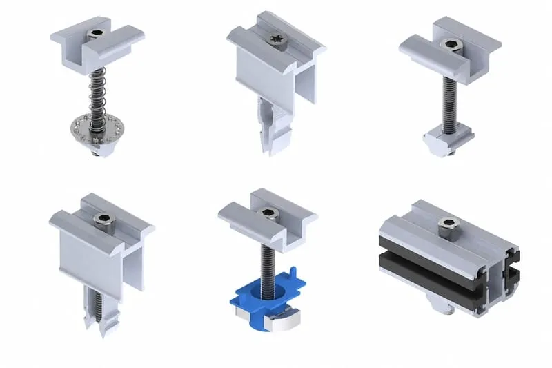
Mid Clamps
Secure adjacent module edges to the rail and, where the product is designed to do so, establish the required module-to-module gap and electrical bonding path.
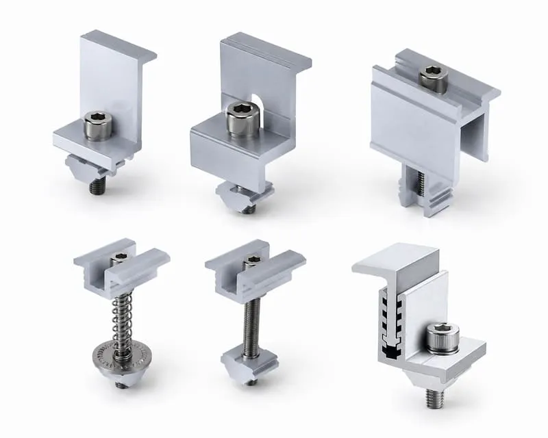
End Clamps
Secure the outside module edge at the end of a row. The clamp height or adjustment range must match the approved module frame and the rail interface.
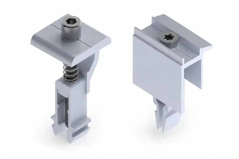
Combined / Adjustable Clamps
Some systems use one adjustable clamp across several frame heights or for both mid and end positions. The stated range and system compatibility still apply.
Verify the Module, Rail and Fastening Interface Together
A clamp can fit the module frame and still be wrong for the rail, bolt, click-in base or approved system family.
Module Frame
Frame height, frame geometry, clamp contact surface and the module manufacturer's permitted clamp zone.
Rail / Support Profile
Rail channel or support geometry and the product family for which the clamp is documented.
Fastening Interface
Bolt thread and length, channel nut, spring element or click-in base plus the specified tightening method.
Bonding & Installation
Required torque, bonding/grounding function, orientation, reuse restrictions and other system-specific instructions.
Finish Is a Variant; Materials Are Product-Specific
Black and natural finishes do not create different clamp functions. The actual clamp body, fastener, spring or polymer components should be taken from the model drawing or datasheet because material combinations vary by product family.
- Use the actual material and finish listed for the selected clamp model.
- Black anodized versions should be checked against the same working range and system compatibility.
- Confirm fastener material, thread and installation torque from the product documentation.
- Check corrosion and bonding compatibility with the module frame and rail system.
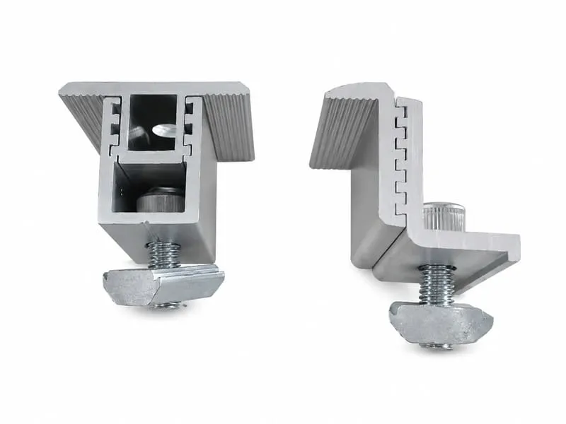
Data to Confirm for the Actual Clamp Model
| Function | Mid, end, combined mid/end, adjustable or another specifically documented module-fixing role. |
|---|---|
| Module compatibility | Framed-module range, frame geometry, clamping zone and any module-orientation restrictions. |
| Rail / system compatibility | Exact rail or support profile and any system exclusions stated by the clamp manufacturer. |
| Fastening | Bolt/thread, channel nut or click-in component plus the specified torque and installation method. |
| Materials & finish | Clamp body, fasteners and auxiliary components as documented for the selected product. |
| Bonding / grounding | Whether the clamp provides an approved bonding function or requires separate system-specific hardware. |
Send the Module and Rail Details
A clamp photo alone is not enough to confirm fit. Send the module datasheet and the rail or support-profile drawing so the working range and interface can be reviewed before the order is finalized.
- Mid, end or combined clamp requirement
- PV module datasheet and frame dimensions
- Rail / support profile cross-section
- Bolt, nut or click-in interface if known
- Required finish and quantity
Solar Panel Clamp Questions
Does a universal clamp fit every PV module and rail?
No. Universal or adjustable clamps have a defined module-frame range and mounting-system compatibility. Check the module, rail/support profile and fastening interface before ordering.
Can the same clamp be used as both a mid and end clamp?
Some product families provide a combined design, while others use separate mid and end clamps. Use only the function and configuration documented for the selected clamp.
What information is needed to confirm a clamp?
Send the module datasheet, frame dimensions, approved clamp-zone information where available, rail/support drawing, fastening interface, required finish and quantity.