
Trapezoidal Roof Solar Mounting
Easy Solar supplies trapezoidal roof solar mounting solutions for commercial, industrial and selected residential sheet metal roofs. The system can be configured with mini rails, short rails, direct-fix brackets, EPDM sealing strips, self-drilling screws, mid clamps, end clamps and grounding accessories for fast, profile-matched PV installation.
- Mini Rail / Short Rail Kits
- Direct-Fix Brackets
- EPDM Waterproof Sealing
- Portrait or Landscape Layout
- Factory-Direct Supply

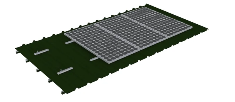
Solar Panel Mounting on Trapezoidal Sheet Metal Roofs
Trapezoidal metal roof solar mounting is designed for profiled sheet metal roofs where the solar attachment must match the rib height, crest width, roof sheet thickness and screw fixing position. Mini rail and direct-fix systems can reduce continuous rail usage and make installation more efficient when the roof profile is suitable.
This page focuses on trapezoidal roof solar mounting and trapezoidal solar mounting keywords. Broader metal roof terms are better handled by the parent Metal Roof Solar Mounting System page, while corrugated and standing seam roof terms should link to their own roof-profile pages.
- For trapezoidal sheet metal, R-panel, tin roof and selected sandwich panel roof applications
- Mini rail, short rail, direct-fix bracket and long rail configurations available by project
- EPDM sealing strips, rubber pads and self-drilling screws for waterproof support
- Suitable for installers, EPC contractors, distributors and OEM project buyers
Trapezoidal Roof Solar Mounting Options
Buyers comparing trapezoidal roof solar mounting usually look at mini rails, short rails, direct-fix brackets and full-rail systems. The best option depends on rib dimensions, module orientation, load requirements and installation preference.
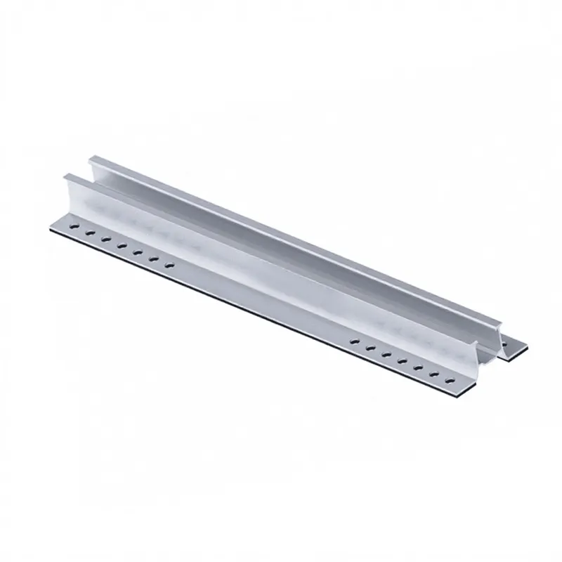
Mini Rail Solar Mount for Trapezoidal Roofs
Short aluminum rails attach to the high ribs of trapezoidal metal sheets and support framed modules with mid and end clamps. This is the primary solution for reduced-rail trapezoidal roof PV mounting.
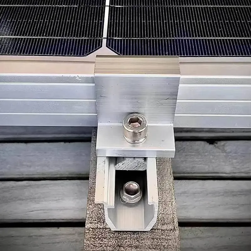
Direct-Fix Trapezoidal Solar Mounting
Direct-fix brackets or compact base rails can simplify installation and reduce long rail usage on suitable rib profiles. This option is useful where a compact, factory-matched kit is preferred.

Long Rail Trapezoidal Roof Racking
Full-length rail systems can be selected for large arrays, specific engineering layouts or projects where standard rail alignment, rail splices and module clamp spacing are preferred.
Why Install Solar on Trapezoidal Metal Roofs with Mini Rails?
Mini rail and short rail structures are often selected because they keep the system compact while still giving installers a clear mounting surface for solar module clamps.
Reduced Rail Material
Short rails can reduce continuous rail length compared with traditional full-rail layouts.
Fast Handling
Compact components are easier to pack, carry and position on industrial metal roofs.
Waterproof Support
EPDM strips and sealing washers support the roof penetration details around fasteners.
Flexible Layouts
Project design can support portrait or landscape module layouts when engineering allows.
Compatible Trapezoidal Roof Applications
Trapezoidal solar mounting should be selected after checking rib height, rib width, crest spacing, roof sheet thickness, screw position, purlin support and required loads.
Trapezoidal Sheet Metal Roofs
Main application for mini rail, short rail and direct-fix PV mounting kits.
R-Panel Metal Roofs
Requires profile measurement before confirming rail width, screw position and sealing details.
Tin Roof Applications
Selected exposed-fastened tin roofs can use mini rails or rails after structure confirmation.
Sandwich Panel Roofs
Requires project review for fastener pull-out strength, panel thickness and load transfer path.
How Solar Panels Are Mounted on Trapezoidal Metal Roofs
This overview supports buyer understanding without replacing engineering review or local installation requirements. Final installation should follow project drawings, torque settings and roof manufacturer guidance.
Measure Rib Profile
Confirm rib height, crest width, spacing and sheet thickness before selecting the rail or bracket.
Position Mini Rails
Align the mini rail or bracket on the high rib according to module orientation and layout.
Seal and Fix
Use EPDM strips or pads with approved screws and correct compression for waterproof support.
Clamp Modules
Secure modules with mid clamps, end clamps and grounding accessories to complete the array.
Trapezoidal Roof Solar Mounting Components
These component terms support the page and can link to accessory pages when separate product pages are available.
Mini Rails
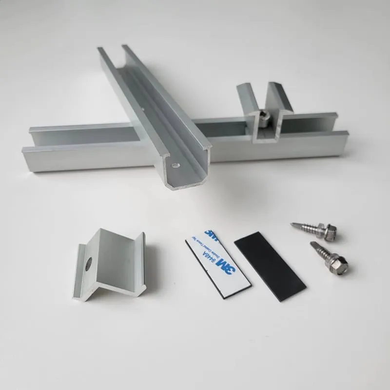
Short AL6005-T5 aluminum rail sections support framed PV modules on trapezoidal roof ribs.
Direct-Fix Brackets
Compact brackets or base supports provide a reduced-rail option for selected trapezoidal profiles.
EPDM Sealing Strips
EPDM rubber strips or pads help seal and protect contact points below rails or brackets.
Mid & End Clamps
Module clamps fix framed solar panels to mini rail, short rail or full-rail structures.
Self-Drilling Screws
Fasteners secure rails or brackets to roof sheets according to roof profile and load requirements.
Grounding Accessories
Grounding clips and bonding parts complete the trapezoidal metal roof PV racking package.
EPDM Sealing and Roof Rib Protection
Most trapezoidal mini rail systems are fixed to the roof sheet with self-drilling screws. EPDM sealing strips, rubber pads and waterproof washers are used to support water resistance and help distribute compression on the roof rib.
Final component choice should confirm roof profile, purlin layout, sheet thickness, corrosion environment, wind load, snow load and module orientation. For sandwich panels, fastener pull-out strength and structural support should be reviewed before quotation.
- EPDM strip or rubber pad options under mini rails and direct-fix brackets
- Self-drilling screws and waterproof washers matched to roof sheet thickness
- Portrait and landscape layouts according to rib direction and module design
- Project-based component list, packaging and factory-direct quotation support

Trapezoidal Roof Solar Mounting Specifications
Final values should be confirmed according to your roof profile, module layout and local engineering requirements.
| Product Name | Trapezoidal Roof Solar Mounting / Trapezoidal Metal Roof Mini Rail PV Racking |
|---|---|
| Roof Compatibility | Trapezoidal sheet metal roofs, R-panel roofs, tin roofs, industrial metal roofs and selected sandwich panel roofs |
| Mounting Options | Mini rail mounting, short rail mounting, direct-fix bracket mounting and long rail configurations |
| Main Components | Mini rails, direct-fix brackets, EPDM sealing strips, mid clamps, end clamps, self-drilling screws, grounding clips and fasteners |
| Material | AL6005-T5 aluminum alloy, SUS304 stainless steel fasteners, EPDM rubber and project-specific accessories |
| Module Layout | Portrait or landscape layout according to module size, rib direction and engineering design |
| Waterproof Support | EPDM sealing strips, rubber pads, waterproof washers and correct fastener compression by roof profile |
| Design Support | Project-based support for rib dimensions, roof sheet thickness, purlin information, wind load, snow load and component list |
| Buyer Type | EPC contractors, solar installers, distributors, wholesalers, OEM customers and metal roof PV project developers |
How to Choose a Trapezoidal Roof Solar Mounting System
Use this checklist to provide the right information for quotation and component matching.
Confirm Roof Profile
Send roof photos, rib height, rib width, crest spacing and roof sheet thickness.
Choose Rail Type
Select mini rail, short rail, direct-fix bracket or long rail according to project design.
Check Structure
Review purlin layout, screw pull-out strength, wind load, snow load and roof condition.
Match Full Kit
Confirm rails, clamps, EPDM strips, screws, grounding, packaging and order quantity.
Factory-Direct Trapezoidal Roof Solar Mounting Solutions
Easy Solar supports project buyers with component matching, OEM packaging and export-ready supply for trapezoidal metal roof solar mounting projects.
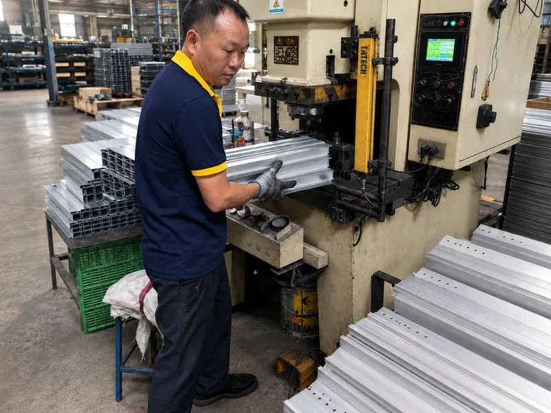
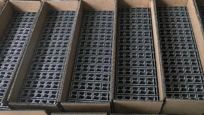
Manufacturing Control
Mini rails, direct-fix brackets, clamps, screws and EPDM strips for project and wholesale orders.
Component Matching
Matched components help installers reduce on-site adjustment and improve trapezoidal roof PV installation efficiency.
Export-Ready Supply
Bulk orders, distributor supply, OEM labels and customized packaging are available for international customers.
Trapezoidal Roof Solar Mounting FAQ
FAQ content targets trapezoidal roof, mini rail, direct-fix, EPDM sealing and quotation search intent.
What is trapezoidal roof solar mounting?
Trapezoidal roof solar mounting is a PV racking solution used to install solar panels on trapezoidal sheet metal roofs. Common parts include mini rails, direct-fix brackets, self-drilling screws, EPDM sealing strips, module clamps and grounding components.
What is a mini rail system for trapezoidal metal roofs?
A mini rail system uses short aluminum rail sections fixed to the high ribs of trapezoidal metal sheets. It can reduce long rail usage and simplify handling when the roof profile and engineering requirements are suitable.
Can trapezoidal roof solar mounting be installed without full-length rails?
Yes. Mini rail and direct-fix bracket systems can be used on selected trapezoidal roofs when rib dimensions, sheet thickness, module layout, wind load and snow load requirements are suitable.
How is waterproofing handled on trapezoidal roof mounts?
Waterproof support is commonly handled with EPDM sealing strips, rubber pads, waterproof washers and correct fastener compression around the screw location.
What information is needed for a trapezoidal roof mounting quote?
Please provide roof photos, rib height, rib width, crest spacing, roof sheet thickness, purlin information, PV module size, layout, wind load, snow load and estimated order quantity.
Request a Trapezoidal Roof Solar Mounting Quote
Send Easy Solar your trapezoidal roof photos, rib dimensions, PV module size and project layout. Our team will help you select suitable mini rails, direct-fix brackets, clamps, EPDM strips, screws and grounding accessories for a factory-direct quotation.
- Trapezoidal roof photos and rib dimensions
- Roof sheet thickness and purlin information
- PV module size and module layout
- Wind load and snow load requirements
- Project capacity and order quantity