
Ground Screws for Solar Mounting
Easy Solar supplies ground screws used as foundation components in ground-mounted PV arrays, solar carports and selected outdoor structures. These solar ground screws can be configured with pipe sockets, flange tops, U-shaped connections, bolt plates or project-specific heads to match the supporting post and structural interface.
- Solar Ground Mount Foundations
- Hot-Dip Galvanized Steel Options
- Multiple Head Connections
- Custom Lengths and Profiles
- Factory-Direct Project Supply
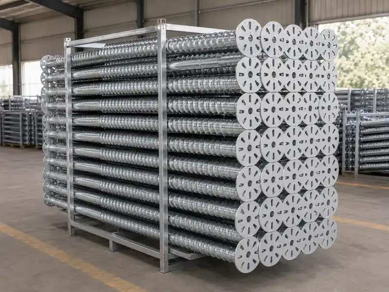
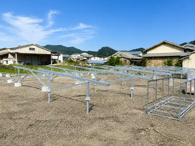
Ground Screws for Solar Mounting Projects
A ground screw is a steel foundation component installed by rotating its shaft and helical section into the soil. The above-ground head or socket then connects to the solar mounting post, support tube, base plate or structural bracket.
Ground screw selection must be based on the project loads, site soil, corrosion environment, installation equipment and structural connection. Easy Solar can discuss standard products and drawing-based ground mount solar foundations for professional PV projects.
- Ground screws for solar mounting systems and solar carports
- Open-top, flange, U-bracket and bolt-plate connection options
- Custom shaft diameter, length, wall thickness and helix geometry
- Compatible post, beam or racking connection according to drawings
Ground Screw Types for Solar Mounting
The head connection and underground geometry should be selected together with the solar structure, loads, soil investigation and installation method.
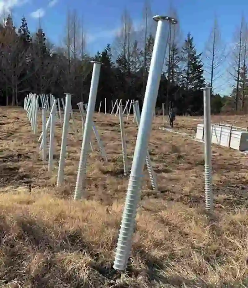
Open-Top Ground Screws
Socket-style screw foundations for inserting a compatible round or shaped support post into the upper opening and securing it with the specified connection method.
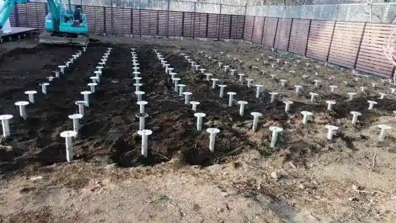
Flange-Top Ground Screws
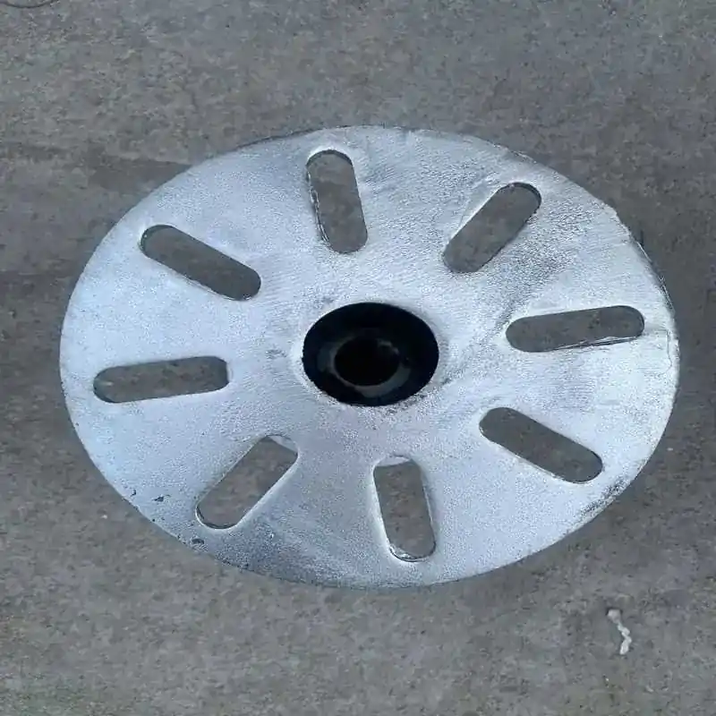
Ground screws with round, square or project-specific flange plates for bolting a compatible solar post, column base or mounting bracket above ground.
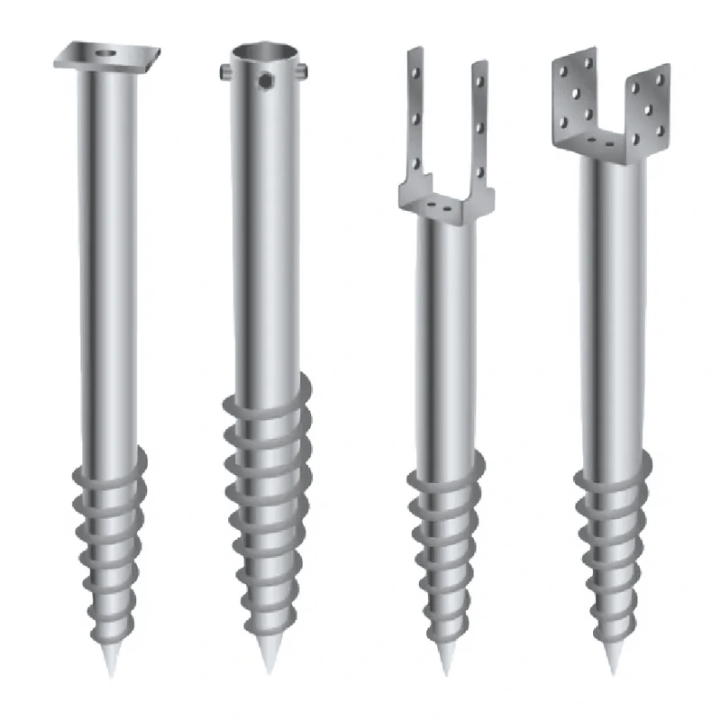
U-Bracket Ground Screws
U-shaped head connections for selected timber, steel or aluminum support interfaces where the structural member and bolt pattern are confirmed.
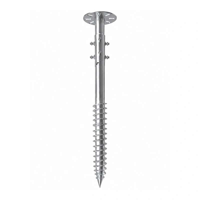
Adjustable Head Connections
Project-specific top assemblies that can provide defined connection or leveling adjustment within the limits of the approved structural detail.
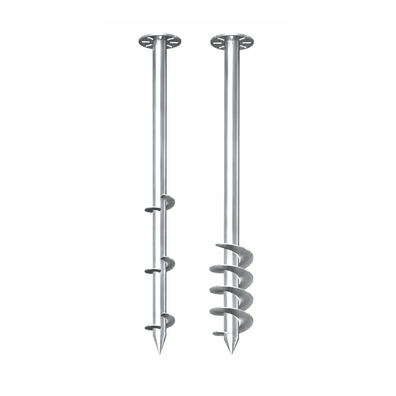
Extended and Reinforced Ground Screws
Longer, wider or reinforced shaft and helix configurations can be discussed where project engineering and site testing require a different foundation geometry.
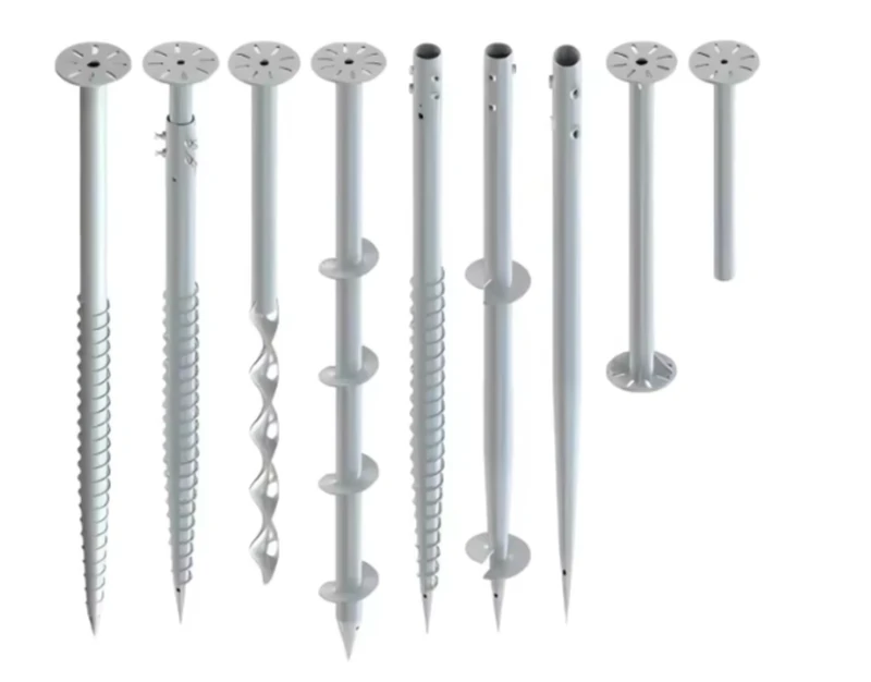
Custom Solar Ground Screws
Drawing-based ground screws with custom length, diameter, helix, flange, bolt pattern, socket, coating, identification and export packaging.
Connecting Ground Screws to Solar Mounting Structures
The top connection transfers forces between the solar mounting structure and the screw foundation. A compatible interface should coordinate the post section, insertion depth, flange, bolt pattern, weld detail, adjustment method and installation clearance.
Provide the supporting-post drawing and base connection. Easy Solar can review whether the project requires an open socket, external flange, internal post, U-shaped bracket, welded plate or another project-specific top connection.
- Round, square, rectangular or custom support-post section
- Socket inside diameter and required insertion depth
- Flange dimensions, thickness, hole pattern and bolt size
- Connection elevation and available leveling adjustment
- Weld, coating and fastener requirements from the approved drawing
Soil Investigation and Foundation Selection
Ground screws are not selected from solar module quantity alone. Soil layers, density, obstructions, groundwater, corrosion conditions, frost requirements, slope and access can affect the screw type and installation method.
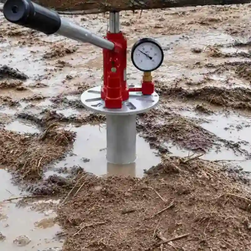
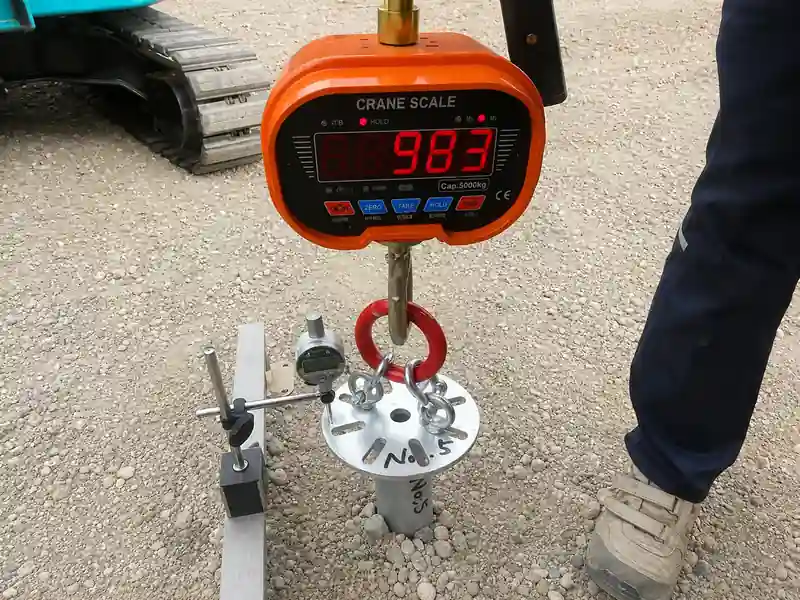
Depending on project scale and local requirements, the responsible project team may need soil data, trial installation, installation-torque records, pull-out or compression testing, lateral testing and structural verification.
- Available geotechnical or soil investigation information
- Trial screw installation at representative site locations
- Required compression, uplift and lateral foundation actions
- Rock, buried obstruction, groundwater and frost considerations
- Site-specific engineering and local approval requirements
Solar Ground Screw Installation Process
Installation should follow the project foundation plan, equipment procedure, testing requirements and structural connection details.
Review Site Data
Confirm soil information, loads, screw layout, access, obstacles and testing requirements.
Set Out Foundation Points
Mark each screw position according to the ground-mount or carport structural drawing.
Drive and Record
Rotate each screw with suitable equipment while checking position, verticality, depth and records.
Connect the Structure
Install posts or base plates, verify alignment and complete the approved mounting connection.
Ground Screw vs Concrete Solar Foundations
Both foundation methods can support solar structures when properly designed. The better option depends on site conditions, project schedule, equipment, engineering and lifecycle requirements.
| Comparison | Ground Screw Foundation | Concrete Foundation |
|---|---|---|
| Site Work | Installed by rotating the screw into suitable soil with specialized equipment | May require excavation, formwork, reinforcement, concrete placement and backfilling |
| Construction Sequence | The approved structural connection can normally proceed after installation and verification | Structural work may depend on the specified concrete curing and inspection sequence |
| Ground Disturbance | Can reduce excavation and spoil generation at suitable sites | Often involves more excavation and material handling |
| Removal | May be removable where the screw and project conditions allow | Removal usually requires breaking and disposing of the concrete foundation |
| Site Limitations | Soil, rock, buried obstructions, corrosion and installation access require assessment | Excavation, groundwater, curing conditions, concrete access and spoil handling require assessment |
| Engineering | Requires project loads, soil assessment, testing and connection verification | Requires project loads, geotechnical design, reinforcement and concrete verification |
Compression, Uplift and Lateral Load Requirements
Ground-mounted solar arrays transfer more than vertical weight into their foundations. Wind and structural geometry can create compression, uplift, lateral and moment actions at the support points.
Ground screw capacity should not be copied from a generic catalogue value without considering the tested soil and project geometry. The quotation can identify product dimensions, but final design values should come from the project engineering and required site verification.
- Design compression action at each support point
- Wind-related uplift and overturning requirements
- Lateral action and post or flange connection behavior
- Required load-test type, test quantity and acceptance criteria
- Structural verification for the screw shaft, helix, welds and head connection
Galvanized Steel Ground Screw Options
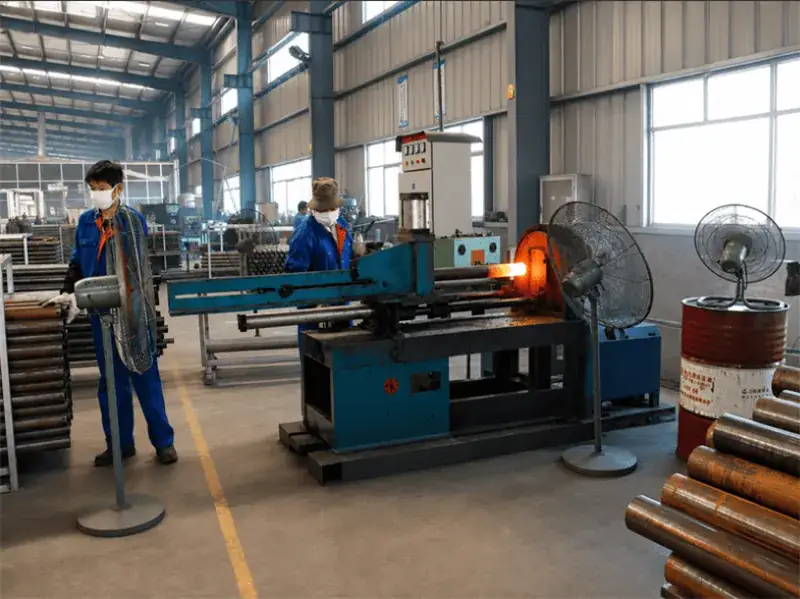
Solar ground screws are commonly produced from formed and welded steel pipe with one or more helical elements and a project-specific top connection. Hot-dip galvanizing is a common outdoor corrosion protection option.
Steel grade, wall thickness, weld detail, galvanizing requirement and any additional protection should be confirmed from the project environment and buyer specification. Corrosive soils may require separate project assessment.
- Steel pipe shaft and welded helix configuration
- Flange, socket, bracket or plate top connection
- Hot-dip galvanized or project-specified coating
- Weld, coating thickness and inspection requirements from the drawing
- Product marking and traceability options for project supply
Ground Screw Foundation Applications
Product geometry and engineering should be matched to the structure, loads, soil and local project requirements for each application.
Ground-Mounted Solar Arrays
Screw foundations for compatible fixed-tilt and project-specific ground solar structures.
View Ground Mount Systems →Solar Carports
Project-specific ground screw foundations for compatible carport posts and base connections.
View Solar Carports →Solar Farm Fencing
Ground screw interfaces for selected mesh or chain-link fence posts and perimeter structures.
Outdoor Support Structures
Project-specific foundations for selected lightweight structures, equipment supports and walkways.
How to Select a Solar Ground Screw Foundation
Begin with the structure and site information, then finalize the underground geometry, top connection, testing plan and project quantity.
Define Project Loads
Provide structural reactions or the information required for the project foundation design.
Review Soil and Site
Provide available geotechnical data, soil description, groundwater, slope and access conditions.
Match the Top Connection
Confirm the support post, socket, flange, bracket, bolt pattern and connection elevation.
Confirm Testing and BOM
Define trial installation, load tests, quantity, spare parts, labels and shipment grouping.
How Solar Ground Screws Connect to PV Mounting Structures
The foundation should be coordinated with the complete structure rather than purchased as an isolated steel component.
Ground Solar Mounting Systems
Posts, beams, braces, rails and module supports coordinated with the foundation layout.
View Ground Systems →Solar Mounting Accessories
Rails, clamps, brackets, fasteners, grounding components and related project hardware.
View Accessories →Grounding and Bonding Parts
Grounding lugs and clips selected separately for the PV mounting and electrical bonding design.
View Grounding Parts →Custom Ground Screws for Solar Mounting
Easy Solar can discuss standard and drawing-based ground screws for solar mounting projects, distributors and OEM customers. Customization may include shaft dimensions, helix geometry, head connection, flange, holes, coating, product marking and packaging.
Final feasibility depends on the approved drawing, material, manufacturing process, testing requirements and order quantity. Site-specific engineering values should not be replaced by manufacturing drawings alone.
- Custom shaft diameter, length and wall thickness
- Custom helix diameter, pitch, quantity and welded position
- Open socket, flange, U bracket, plate and bolt-pattern options
- Galvanizing and project-specific corrosion protection requirements
- Product marking, counted bundles, pallets and export packaging
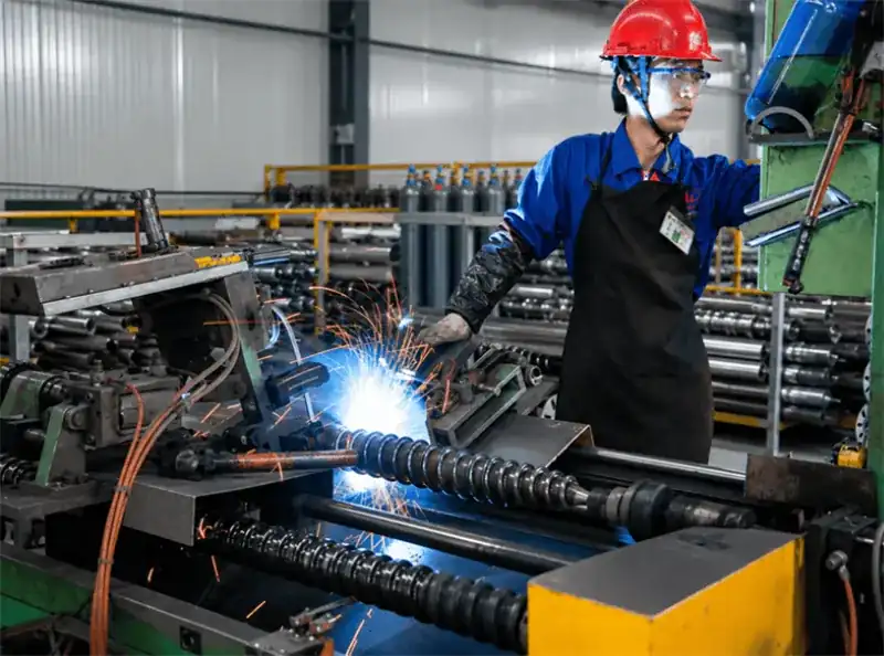
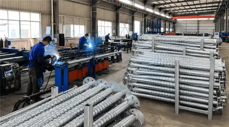
Solar Ground Screw Manufacturer and Supplier
Easy Solar supports professional buyers with steel processing, welding, galvanizing coordination, dimensional inspection and export-ready project packaging.
Steel Processing and Welding
Shafts, helices, flanges, sockets and brackets can be processed according to the confirmed product drawing and manufacturing requirements.
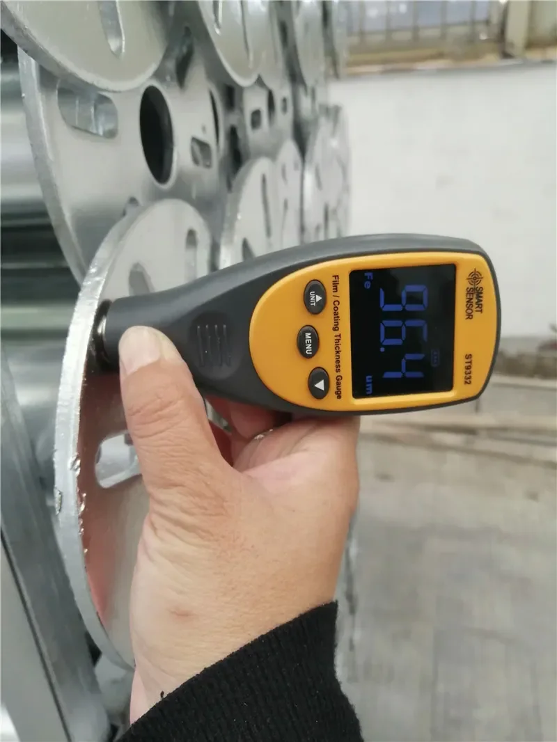
Coating and Product Inspection
Dimensions, welds, head connections, hole patterns, coating and product identification can be checked against the confirmed specification.
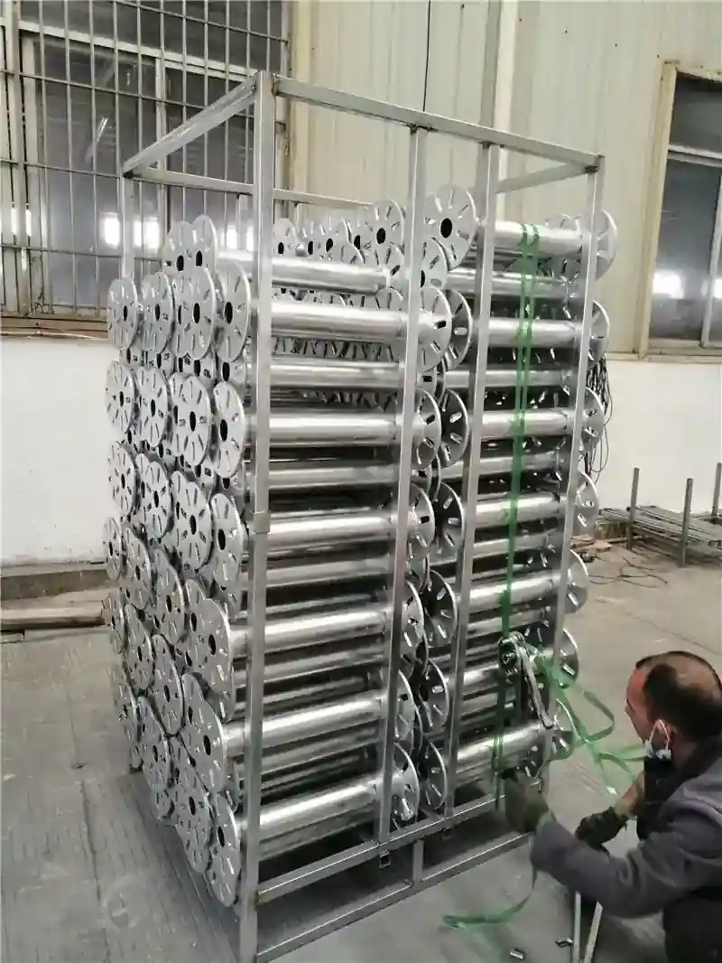
Bulk and Project Packaging
Ground screws can be bundled and packed by model, foundation row, project area, shipment batch or OEM label requirement.
Solar Ground Screw Specifications
Final dimensions and performance requirements depend on the project structure, soil, loads, connection design, corrosion environment and site testing.
| Product Name | Ground Screws for Solar Mounting / Solar Ground Screw Foundation |
|---|---|
| Applications | Ground-mounted solar arrays, solar carports, selected fencing and project-specific outdoor structures |
| Ground Screw Types | Open-top socket, flange-top, U-bracket, plate connection, adjustable head and drawing-based custom screw foundations |
| Material | Steel grade and product construction according to the confirmed project or product drawing |
| Corrosion Protection | Hot-dip galvanizing or project-specific coating according to the installation environment |
| Shaft Options | Custom diameter, length, wall thickness, taper and pipe profile available upon technical review |
| Helix Options | Custom helix diameter, pitch, quantity, thickness and welded position according to the foundation design |
| Top Connection | Socket, flange, U bracket, plate, threaded or project-specific interface matched to the supporting structure |
| Testing Information | Trial installation, installation records and load testing requirements should be defined by the project team |
| Customization | Dimensions, head type, holes, bolt pattern, coating, product marking, labels and packaging available upon discussion |
| Buyer Type | EPC contractors, solar installers, mounting-system suppliers, distributors, OEM buyers and project developers |
Request a Solar Ground Screw Quote
Send Easy Solar the solar structure, support-post drawing, site and soil information, project loads, screw layout, coating requirement and quantity. Our team will review the manufacturing scope and prepare a factory-direct quotation.
- Solar ground-mount or carport application
- Support-post and top-connection drawing
- Available soil and geotechnical information
- Compression, uplift and lateral design actions
- Shaft, helix, flange and coating requirements
- Trial installation and load-test requirements
- Quantity, labels, packaging and delivery schedule
Solar Ground Screw FAQ
Common questions from solar installers, EPC contractors, distributors and ground-mount project buyers.
What is a solar ground screw?
A solar ground screw is a steel foundation component rotated into suitable soil and connected to the above-ground post, base plate or supporting structure of a ground-mounted PV system.
What are ground screws for solar mounting made from?
They are commonly manufactured from steel pipe with welded helical elements and a project-specific top connection. Material, wall thickness and coating should follow the confirmed specification.
Are solar ground screws suitable for every soil type?
No. Suitability depends on the soil profile, rock and obstructions, groundwater, corrosion conditions, project loads, installation equipment and site-specific verification.
Do ground screws require concrete?
The screw foundation itself is installed mechanically without pouring a conventional concrete footing. The complete project may still contain concrete in other structures or details.
Is load testing required for ground screws?
Testing requirements depend on the project scale, soil information, local rules and the responsible engineer's design. Trial installation and site-specific testing may be required.
Can ground screws be used for solar carports?
They can be considered for compatible solar carport structures when the post connection, foundation loads, soil, vehicle-area requirements and project engineering are confirmed.
What ground screw head connections are available?
Options can include open sockets, flange tops, U-shaped brackets, bolt plates and custom interfaces matched to the solar support post or base connection.
Can solar ground screws be removed?
Some screw foundations may be removable by reversing the installation process, subject to the product condition, site access, soil and project requirements.
Can you manufacture custom ground screws?
Yes. Shaft length and diameter, wall thickness, helix geometry, flange, socket, holes, coating, marking and packaging can be discussed from approved drawings.
Can the same ground screw be used for solar arrays and fencing?
Not automatically. Solar arrays and fences create different loads and use different post connections. Each application should be matched to its own structural and site requirements.
What information is needed for a quotation?
Please provide the application, support-post drawing, soil or geotechnical information, project loads, screw layout, product dimensions, top connection, coating, quantity and packaging needs.