
Solar Rail Splice Kits
Easy Solar supplies solar rail splice kits for joining compatible aluminum PV mounting rail sections. Product options include internal rail splices, external splice plates, sliding connectors, bolted splice kits and custom aluminum rail joiners for roof, ground, carport and selected balcony solar mounting systems.
- Internal & External Splices
- Rail Profile Matching
- Bolts & Connection Hardware
- Custom Aluminum Joiners
- OEM & Project Supply
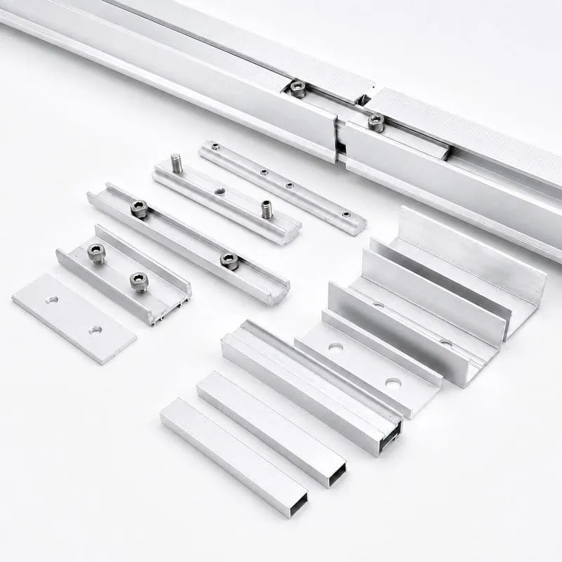
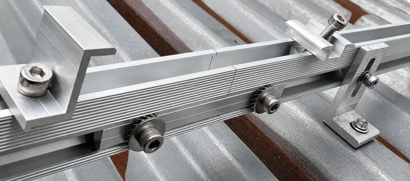
Solar Rail Connectors for Long PV Module Rows
Solar rail splice kits join compatible mounting rail sections where one continuous rail length is not practical for production, transportation or site installation. The connector helps align the rail sections and creates the specified mechanical connection between them.
A splice connector must match the rail cross-section, internal cavity or external surface, hole or slot position, bolt type and installation method. Easy Solar can supply standard rail joiners or discuss custom splice length, wall thickness, holes, fasteners, finish and project packaging.
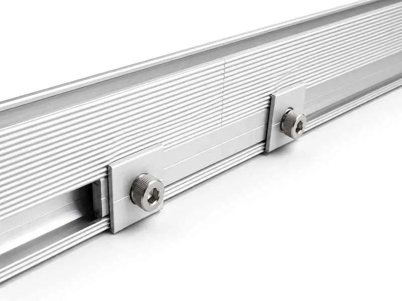
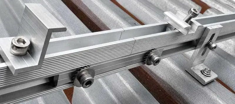
- Internal and external solar rail splice connector options
- Compatibility matching for aluminum PV mounting rail profiles
- Bolted, sliding and project-specific connection methods
- Custom extrusion, plate, holes, fasteners and packaging
Solar Rail Splice Kit Types
Select the splice according to the rail cavity, outer profile, connection direction, fasteners, installation access and project design.
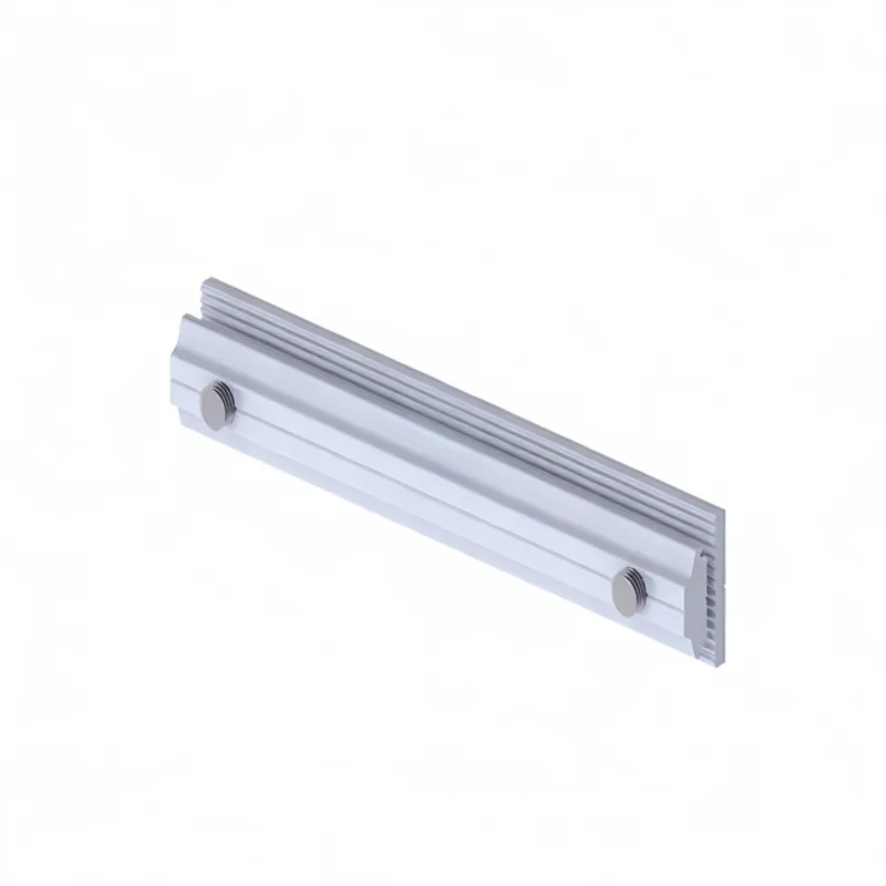
Internal Solar Rail Splices
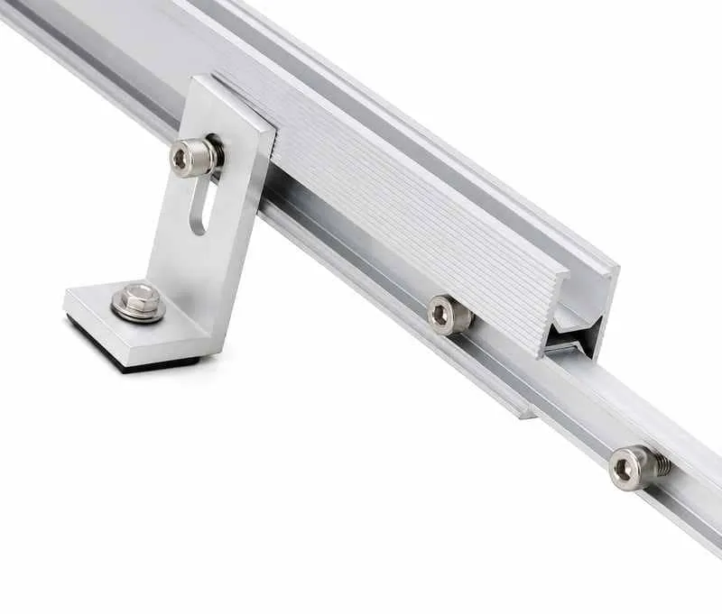
Internal connectors slide into compatible rail cavities and are fixed or retained according to the rail and splice design.
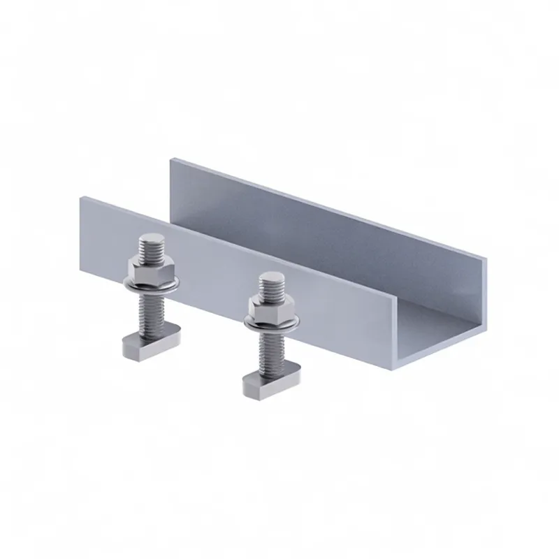
External Rail Splice Plates
External plates bridge the joint from the side, bottom or another approved rail surface using compatible bolts and nuts.
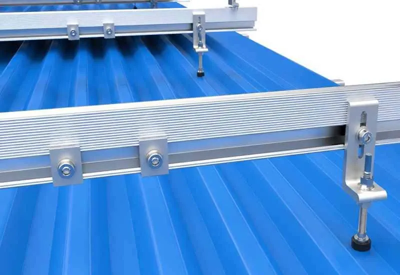
Sliding Rail Joiners
Profile-matched sliding joiners support rail alignment and may use a retained, friction or fastened interface according to the product design.
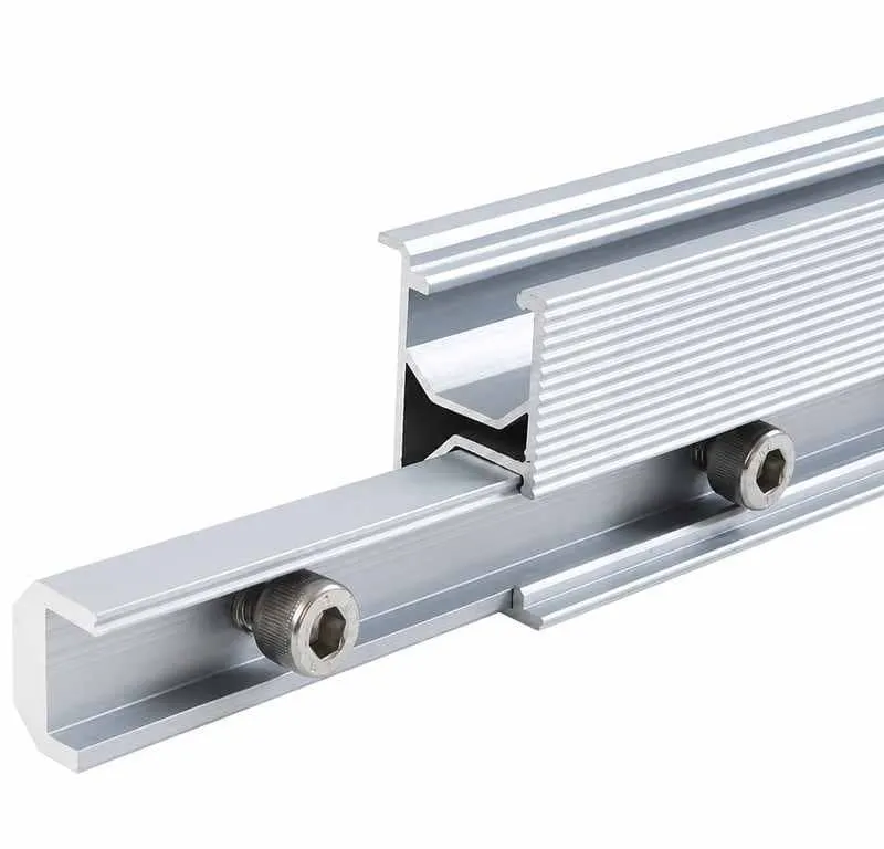
Bolted Rail Splice Kits
Connector sets supplied with compatible bolts, nuts or channel hardware for specified rail holes, slots or splice interfaces.
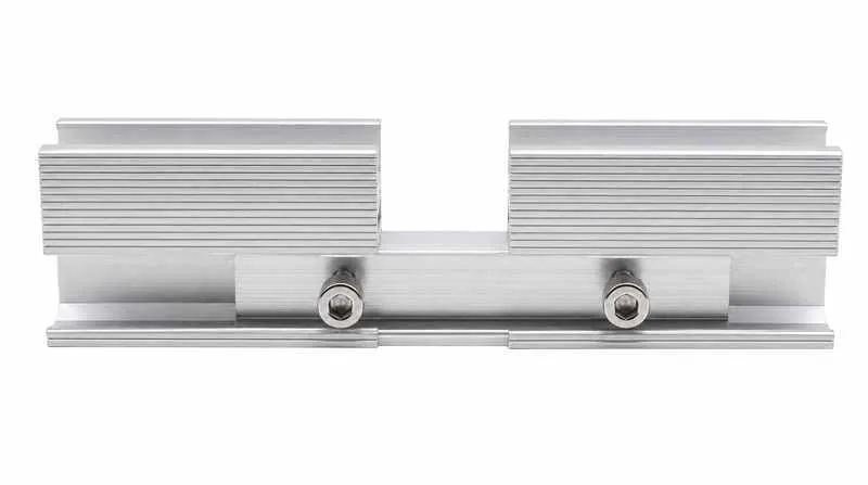
Reinforced Splice Options
Longer or project-specific connector profiles can be discussed where the confirmed rail system requires a different splice geometry.
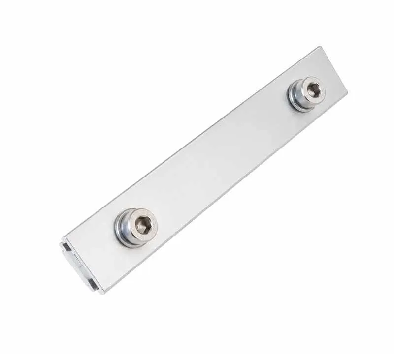
Custom Solar Rail Splices
Drawing-based extrusion or plate connectors with custom profile, length, thickness, holes, slots, finish, fasteners and packaging.
Internal vs External Solar Rail Splices
Both styles can join rail sections, but they use different contact surfaces and installation access.
| Comparison | Internal Splice | External Splice |
|---|---|---|
| Installation Position | Fits inside a compatible rail cavity | Fits on the side, bottom or another approved outer rail surface |
| Profile Matching | Requires close matching with internal rail geometry | Requires matching with outer surfaces, holes, slots and bolt interfaces |
| Fastener Access | May use side screws, bolts, retained features or profile-specific locking | Usually provides direct access to external bolts, nuts or channel hardware |
| Visible Appearance | Most of the connector is concealed within the rail | The connector plate remains visible on the outside of the joint |
| Quotation Information | Rail cavity drawing, splice insertion depth, retention method and length | Outer rail dimensions, plate location, hole pattern, bolts and connector length |
Matching Rail Splices to Aluminum Rail Profiles
Rail splice compatibility depends on the exact rail cross-section. Similar-looking solar rails can have different cavities, ribs, channels, wall thicknesses and bolt slots.
Provide the rail drawing or a measured cross-section, including internal and external dimensions. A splice should not be selected only from rail height, rail width or product appearance.
- Rail height, width, wall thickness and cavity dimensions
- Internal ribs, channels, lips and insertion clearances
- External slot, side wall or bottom surface used by the splice
- Connector insertion length and joint position
- Required bolts, nuts, washers or retaining features
Rail Alignment, Joint Position and Fastening
A rail splice should support the intended alignment of two rail sections at the joint. Rail ends, connector position, fasteners and nearby supports must follow the selected mounting-system detail.
The project drawing should define where splices are permitted, how the connector is centered or positioned, and whether a gap or other installation allowance is required.
- Rail ends cut square and prepared for the selected connector
- Splice inserted or positioned to the specified depth
- Rail tops and module-support surfaces aligned at the joint
- Fasteners installed in the specified holes or slots
- Joint location coordinated with supports, clamps and rail loading design
Rail Expansion, Joint Gaps and Long-Row Layouts
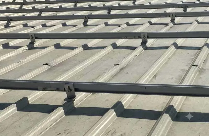
Long rail rows may require project-specific consideration of joint gaps, thermal movement, support locations and electrical bonding. These details should be defined by the selected mounting system and project engineering documents.
A rail splice kit should not be used to invent a joint detail that is absent from the mounting design. Easy Solar can manufacture the connector, but the required joint spacing and structural arrangement should come from the approved project specification.
Mechanical Rail Splices and Electrical Bonding
A rail splice creates a mechanical connection, but it should not automatically be assumed to provide every required electrical bonding function. The project grounding design should confirm whether the selected joint is bonded through an approved interface or requires additional hardware.
Where specified, rail bonding may use compatible clips, lugs, jumpers or other components. Mechanical splice hardware and grounding hardware should be listed separately in the bill of materials unless the system documentation confirms a combined function.
- Mechanical rail-joint method identified
- Electrical bonding requirement confirmed separately
- Bonding lug, clip or jumper selected where required
- Conductor routing coordinated with rail and module layout
- Grounding parts counted separately in project packaging
Aluminum Solar Rail Splice Connector Options
Solar rail splice connectors are commonly produced from aluminum extrusion or plate where the connector must match an aluminum mounting rail. Stainless steel bolts, nuts or screws may be included according to the connection design.
Alloy, temper, wall thickness, plate thickness, anodizing, mill finish and fastener material should be confirmed from the product drawing and buyer specification.
- Extruded aluminum internal splice profiles
- Aluminum external splice plates and custom connector shapes
- Mill, anodized or project-specific finish options
- Compatible stainless steel or project-specified fasteners

Components Used with Solar Rail Splice Kits
Splice connectors should be selected with the rail profile, fasteners, grounding parts, module clamps and complete PV mounting system.
Solar Mounting Rails
Rail cross-sections matched to internal or external splice connector geometry.
View Mounting Rails →Bolts & Fasteners
Bolts, nuts, screws and washers selected for the rail and splice interface.
View Fasteners →Grounding Parts
Grounding lugs, clips or bonding jumpers used where the electrical design requires.
View Grounding Parts →Solar Panel Clamps
Mid and end clamps positioned according to module layout and rail-joint restrictions.
View Solar Panel Clamps →Mounting Brackets
Rail supports and bracket positions coordinated with splice-joint locations.
View Mounting Brackets →Solar Mounting Kits
Project packages combining rails, splices, clamps, fasteners and grounding hardware.
View Mounting Kits →Solar Rail Splice Kits for PV Mounting Systems
Rail joiners can be supplied for different mounting-system layouts when the rail profile and project connection detail are compatible.
Roof Solar Mounting
Rail splices for long rooftop module rows and transport-length rail sections.
View Roof Systems →Ground Solar Mounting
Connector options for compatible ground-mount rails and module-support profiles.
View Ground Systems →Solar Carport Systems
Rail-joint hardware for standard and selected waterproof carport rail profiles.
View Carport Systems →Balcony Solar Mounting
Compact rail connectors for compatible balcony mounting profiles and layouts.
View Balcony Systems →How to Select Solar Rail Splice Kits
Begin with the rail cross-section and approved joint detail, then confirm splice geometry, fasteners, quantity and packaging.
Provide the Rail Profile
Send the rail cross-section, dimensions, cavity, ribs, slots and wall thickness.
Confirm the Joint Method
Identify internal, external, sliding, bolted or project-specific splice connection.
Match Fasteners and Finish
Specify bolts, nuts, screws, holes, material, anodizing and installation access.
Prepare the Rail BOM
Confirm rail lengths, number of joints, splice quantity, packaging and delivery plan.

Custom Solar Rail Splice Manufacturing
Easy Solar supports standard rail splice supply and drawing-based projects for installers, distributors, EPC contractors and OEM buyers. Custom work can be discussed for extrusion profile, plate shape, length, thickness, holes, slots, finish, fasteners and packaging.
Production details may include extrusion, cutting, machining, drilling, punching, anodizing, fastener matching, dimensional inspection and project-set packaging. Final feasibility depends on the rail drawing, connector design, material and order quantity.
- Custom internal cavity profile or external splice plate
- Custom connector length, wall thickness, holes and slots
- Custom bolt, nut, screw and washer combinations
- Mill, anodized or project-specific surface finish
- OEM labels, counted bags, bundled rail sets and export packaging
Solar Rail Splice Manufacturer and Supplier
Easy Solar supports professional buyers with aluminum profile processing, fastener matching, dimensional inspection and export-ready project delivery.
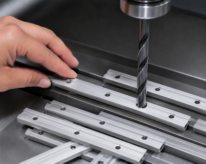
Extrusion & Plate Processing
Internal profiles and external plates can be processed according to confirmed rail geometry, connector length, holes and slots.
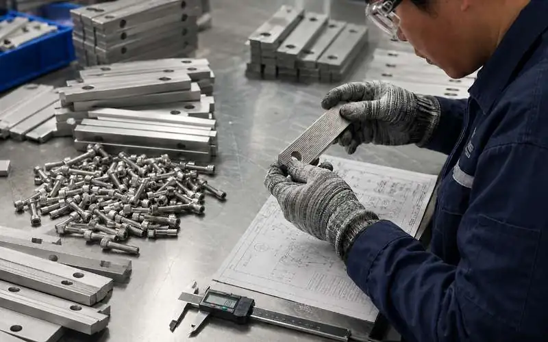
Profile Fit & Dimension Inspection
Connector dimensions, insertion fit, hole positions, fastener interfaces and surface finish can be checked against the confirmed drawing.
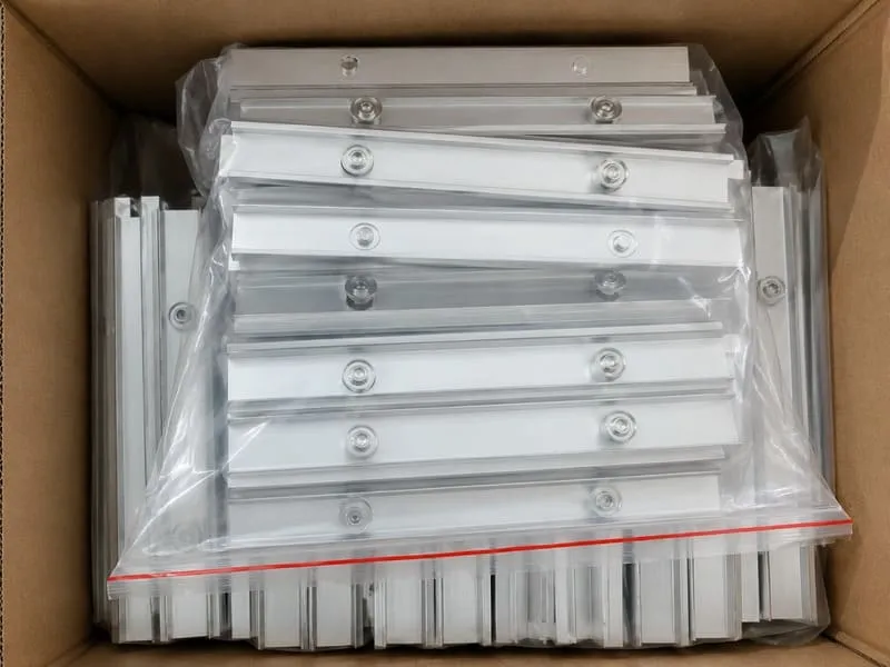
Counted & Project Packaging
Splice kits can be packed by rail model, connection type, project area, counted bag, carton quantity or OEM label requirement.
Solar Rail Splice Kits Specifications
Final specifications depend on the rail profile, joint method, connector geometry, fasteners, finish and project installation detail.
| Product Name | Solar Rail Splice Kits / Solar Rail Connectors / PV Mounting Rail Joiners |
|---|---|
| Splice Types | Internal splices, external splice plates, sliding joiners, bolted connectors, reinforced connectors and custom rail splices |
| Applications | Roof, ground, carport and selected balcony solar mounting systems with compatible aluminum rails |
| Rail Compatibility | Matched according to rail cross-section, internal cavity, external surface, slots, ribs and wall thickness |
| Material Options | Aluminum extrusion, aluminum plate or project-specific material according to connector design |
| Fastener Options | Compatible bolts, nuts, screws, washers or retaining parts according to the rail and splice interface |
| Surface Finish | Mill finish, anodized or project-specific surface treatment |
| Grounding Note | Mechanical rail splice and electrical bonding requirements should be confirmed separately in the project design |
| Customization | Profile, length, thickness, holes, slots, material, finish, fasteners, labels and packaging available upon discussion |
| Buyer Type | EPC contractors, solar installers, distributors, wholesalers, OEM customers and PV project developers |
Request a Solar Rail Splice Quote
Send Easy Solar the rail cross-section, joint method, connector drawing, fasteners, finish and project quantity. Our team will help review the splice compatibility and prepare a factory-direct quotation.
- Rail cross-section and profile dimensions
- Internal or external splice requirement
- Connector length, thickness, holes and slots
- Bolt, nut, screw and washer requirements
- Material and surface finish
- Rail lengths, joint count and project quantity
- Packaging, labels and delivery plan
Solar Rail Splice Kits FAQ
Common questions from solar installers, EPC contractors, distributors and PV rail hardware buyers.
What are solar rail splice kits?
Solar rail splice kits are connector assemblies used to join compatible aluminum PV mounting rail sections in longer module rows.
What is the difference between an internal and external rail splice?
An internal splice fits inside the rail cavity. An external splice plate bridges the joint from an outer rail surface using compatible bolts or other hardware.
Are rail splice kits compatible with every solar mounting rail?
No. Compatibility depends on the exact rail cross-section, cavity, ribs, slots, wall thickness, connector geometry and fasteners.
How do I confirm the correct rail splice size?
Provide the rail cross-section, internal and external dimensions, wall thickness, joint method, connector length and fastener details.
Do rail splice kits include bolts and nuts?
Bolts, nuts, screws and washers can be included when they are part of the confirmed splice design and bill of materials.
Can a rail splice be installed anywhere along the rail?
Splice position should follow the selected mounting-system and project engineering detail, including support locations, module clamps and permitted rail-joint zones.
Should there be a gap between two rail sections?
Joint gap or installation allowance depends on the mounting system and project design. Do not assume that every rail joint requires zero gap.
Does a mechanical rail splice provide electrical bonding?
It should not automatically be assumed to satisfy every bonding requirement. The project grounding design should confirm whether separate bonding hardware is required.
Can you manufacture custom solar rail splice connectors?
Yes. Custom extrusion profiles, plates, lengths, thicknesses, holes, slots, fasteners, finishes and packaging can be discussed from rail and splice drawings.
Can rail splice kits be packed with solar mounting rails?
Yes. Splice connectors and fasteners can be counted and packed by rail model, project area, bundle, carton or complete solar mounting kit.
What information is needed for a quotation?
Please provide the rail cross-section, joint method, splice drawing, connector dimensions, fasteners, material, finish, rail lengths, joint count, quantity, packaging and project application.