
What Is Solar Racking? A Complete Guide to Solar Panel Mounting Systems
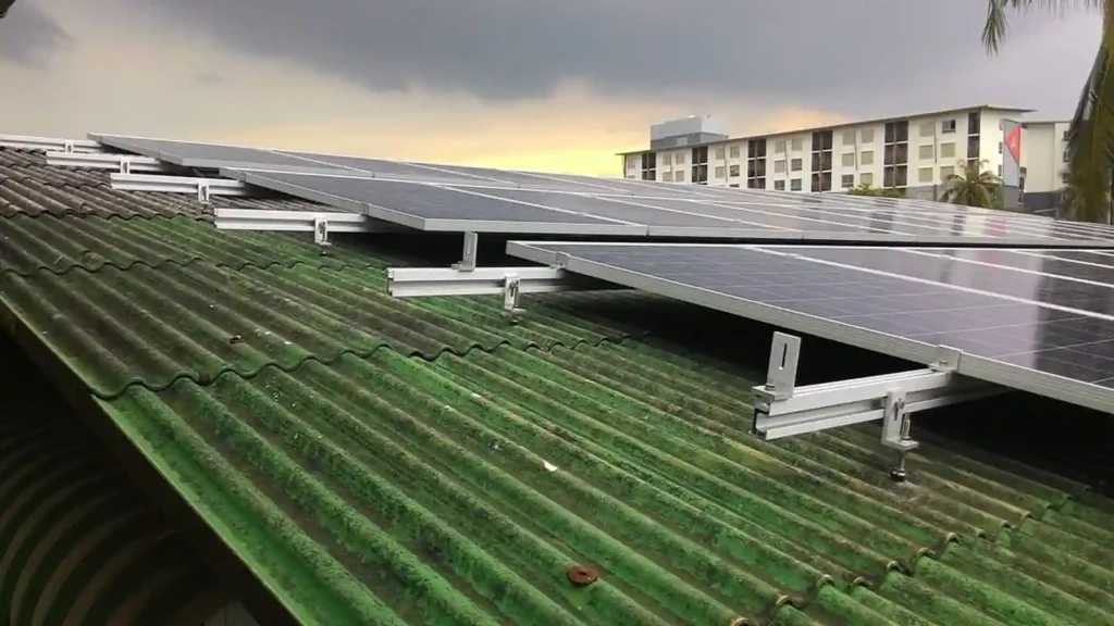
Solar racking is the structural system that supports photovoltaic modules, holds them in the required position, and transfers loads from the solar array into a roof, supporting frame, ground foundation, or other load-bearing structure.
Also called a solar mounting system, PV mounting system, or solar panel racking system, it is one of the most important mechanical parts of a photovoltaic installation.
The correct racking system depends on much more than module quantity. Roof type, soil conditions, PV module dimensions, array layout, wind and snow conditions, tilt angle, corrosion environment, installation access, and structural requirements can all affect the final mounting configuration.
This guide explains how solar racking works, the major mounting system types, common components and materials, and the information needed to select a suitable system for a real PV project.
Solar Racking at a Glance
If you only need the short answer, the table below summarizes the basics.
| Question | Short Answer |
|---|---|
| What is solar racking? | The structural system that supports PV modules and transfers their loads into a roof, frame, or foundation. |
| What are the main types? | Roof mount, ground mount, solar carport, agrivoltaic solar mount and balcony mounting system. Ground systems may also be fixed-tilt or tracking. |
| What are the main components? | Rails or purlins, module clamps, roof attachments, posts, beams, base, foundations, fasteners, grounding parts, and cable-management components. |
| What materials are commonly used? | Aluminum, galvanized stee and stainless-steel hardware. |
| What determines the correct system? | Installation surface, module dimensions, layout, wind, snow, roof or soil conditions, tilt, clearance, and project environment. |
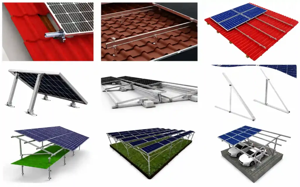
What Is Solar Racking?
Solar racking is the load-bearing structure used to position and secure PV modules.
The terms solar racking system, solar mounting system, solar panel mounting system, PV mounting system, and solar panel mounting structure are frequently used for structures that perform the same general function.
A mounting system can range from a relatively simple rooftop assembly to a large engineered structure.
For example, a pitched-roof installation may consist of roof attachments, aluminum rails, module clamps, fasteners, and grounding components.
A ground-mounted solar project can require foundations, columns, beams, braces, rails or purlins, clamps, and multiple connection components.
A solar carport adds structural columns and canopy beams, while an agrivoltaic system may require significantly more ground clearance to accommodate crops, workers, livestock, or agricultural machinery.
What all of these systems have in common is a structural load path.
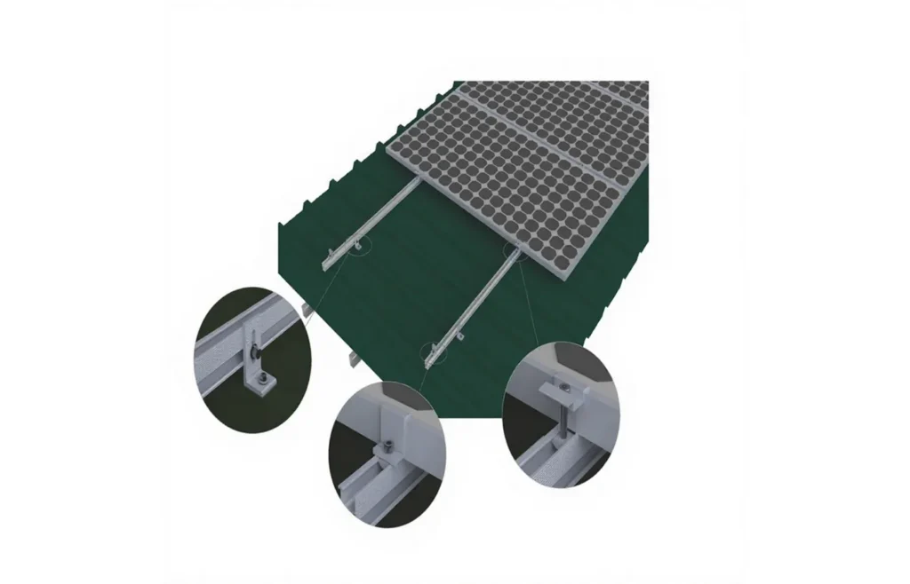
A simplified load path can be described as:
PV Module → Module Clamp → Rail or Purlin → Attachment or Structural Beam → Roof or Foundation
This is why solar racking should not be considered simply as a collection of brackets.
It is a complete structural system.
For buyers who are still determining the correct configuration, the main solar mounting systems section provides an overview of the available application categories.
What Does a Solar Mounting System Do?
A solar mounting system performs several functions at the same time.
1. Support and Secure the PV Modules
The most obvious function is keeping the modules in the designed position.
Clamps, rails, brackets, beams, posts, and foundations have to work together as an assembly rather than as unrelated components.
A weak or incompatible connection at one part of the load path can affect the entire mounting configuration.
2. Transfer Wind, Snow, and Dead Loads
PV modules, rails, beams, and other components have their own weight.
The system may also be exposed to wind uplift, downward wind pressure, lateral forces, and snow loads.
These forces eventually have to be transferred into the roof structure or ground foundation.
For this reason, rail span, attachment spacing, column spacing, bracing, and foundation reactions are part of mounting-system engineering.
3. Control Module Position, Orientation, and Tilt
The mounting system determines how modules are arranged.
This can include:
- Portrait or landscape orientation
- Row spacing
- Module spacing
- Fixed tilt angle
- Roof-following installation
- Ground clearance
- Maintenance access
On pitched roofs, the module angle often follows or is influenced by the roof slope.
Flat-roof and ground-mounted systems generally provide more flexibility for selecting a dedicated tilt angle.
4. Create a Compatible Mechanical Interface
The mounting structure also connects many different components together.
Module frame thickness must match the selected clamp.
The clamp must match the rail channel.
The rail must match the roof attachment, bracket, beam, or structural support.
Fastener size and connection geometry also need to be compatible.
This is why a mounting component should not be selected only because its nominal dimensions appear similar to another part.
5. Support Long-Term Outdoor Durability
Solar mounting systems are exposed outdoors for many years.
Material selection, surface treatment, fasteners, sealing components, and corrosion compatibility therefore matter.
Coastal, industrial, or high-humidity environments require different corrosion considerations from ordinary inland installations.
What Are the Main Components of Solar Racking?
The exact bill of materials depends on the system, but most PV mounting structures use several common component groups.
| Component | Main Function | Typical Applications |
|---|---|---|
| Rails / Purlins | Support module rows and transfer loads into attachments or structural members | Roof, ground, carport, agrivoltaic |
| Mid & End Clamps | Secure framed PV modules to rails or compatible support profiles | Most rail-based systems |
| Roof Attachments | Connect the mounting system to the roof structure or roof profile | Metal, tile, shingle, pitched roof |
| Posts / Columns / Beams | Form the main structural frame | Ground mount, carport, agrivoltaic |
| Foundations | Transfer structural reactions into the ground | Ground screws, piles, concrete |
| Bolts & Fasteners | Connect rails, brackets, clamps, beams, and other components | All mounting systems |
| Grounding / Bonding Parts | Support electrical continuity where required | Module and rail interfaces |
| Cable Management | Support and organize PV cables | Roof, ground, carport, utility PV |
Solar Mounting Rails
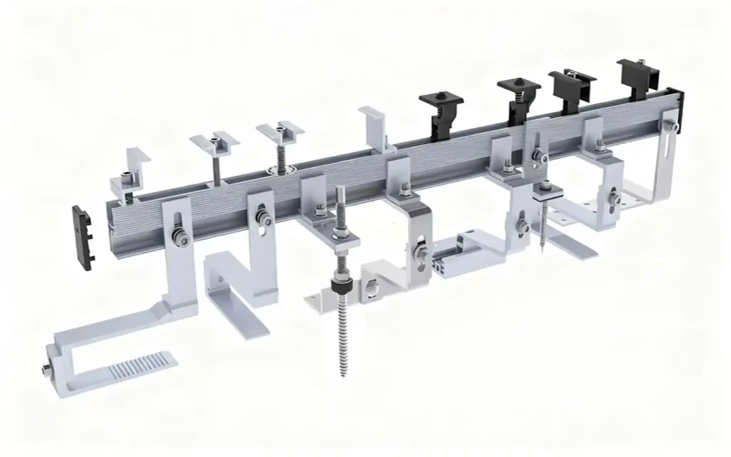
Rails provide the primary module-support and alignment interface in many mounting systems.
Their profile, wall thickness, support span, channels, splice method, and clamp compatibility can vary by application.
For detailed rail options, see solar panel mounting rails.
Module Clamps
Mid clamps secure adjacent modules, while end clamps are typically used at the outer edges of a module row.
Clamp geometry must match both the rail interface and module frame.
See solar panel clamps for more component-level information.
Roof Attachments and Brackets
Roof mounting may use roof hooks, L feet, hanger bolts, metal-roof brackets, standing-seam clamps, flashing components, or other project-specific interfaces.
The correct attachment depends on the roof profile, structural connection, and waterproofing method.
Fasteners
Bolts, nuts, washers, T-bolts, self-tapping screws, and other fasteners connect the mounting structure.
Fastener material and dimensions should be matched to the mounting system and installation environment.
Grounding and Bonding Components
Grounding clips, bonding washers, and grounding lugs may be incorporated into the mounting assembly according to the electrical design and applicable project requirements.
Additional component categories can be found in the solar mounting accessories section.
What Are the Main Types of Solar Mounting Systems?
One of the easiest ways to classify solar racking is by where and how the structure is installed.
The major categories include roof mounting, ground mounting, solar carports, agrivoltaic mounting, and balcony mounting.
Roof Solar Mounting Systems
Roof solar mounting systems connect PV modules to an existing building roof.
The correct mounting method changes significantly according to roof material and geometry.
Common roof applications include:
- Metal roofs
- Tile roofs
- Shingle roofs
- Pitched roofs
- Flat roofs
- Standing-seam roofs
- Corrugated roofs
- Trapezoidal metal roofs
Metal roofs may use L feet, hanger bolts, triangle solar mount, adjustable solar panel mount, mini rails, or standing-seam clamps.
Tile roofs commonly use roof hooks and rails.
Shingle installations normally require a structural attachment and suitable weather-sealing detail.
Flat roofs may use mechanically attached structures, ballast-based systems, or project-specific combinations.
For commercial rooftops, see the dedicated flat roof solar mounting system section.
Roof projects should consider more than the visible roof covering.
The mounting system may also depend on:
- Roof structure
- Rafter or purlin location
- Roof slope
- Waterproofing
- Wind uplift
- Module layout
- Attachment spacing
- Roof load limitations
- Maintenance pathways
One universal mounting bracket should not be assumed to work across every roof type.
Ground-Mounted Solar Racking
Ground solar mounting systems use a dedicated structural frame and foundation instead of relying on an existing building.
A typical fixed ground structure may include:
- Ground screws, piles, or concrete foundations
- Posts or columns
- Beams
- Braces
- Rails
- Base
- Module clamps
- Structural fasteners
A fixed tilt ground mount solar racking structure holds the modules at a predetermined angle.
Ground-mounted systems can offer greater flexibility in module orientation, tilt, row spacing, and maintenance access.
However, they also introduce considerations that rooftop projects may not have.
These include:
- Soil conditions
- Foundation capacity
- Pile pull-out resistance
- Terrain
- Ground clearance
- Vegetation
- Drainage
- Row-to-row shading
- Equipment access
The foundation should therefore be selected together with the structural system and actual site conditions.
Solar Carport Mounting Systems
A solar carport mounting system combines a PV support structure with a parking canopy.
A typical carport structure can include:
- Foundations
- Base plates
- Structural columns
- Main beams
- Secondary beams or rails
- Braces
- Module clamps
- Connection hardware
Unlike a basic ground-mounted table, a solar carport also has to accommodate people and vehicles below the array.
Important design inputs may include:
- Parking-bay width
- Vehicle clearance
- Column position
- Drive lanes
- Canopy span
- Drainage
- Lighting
- EV charging infrastructure
- Wind and snow conditions
Some projects also require waterproof canopy configurations to control rainwater below the PV modules.
Agrivoltaic Mounting Systems
Agrivoltaic PV mounting systems combine photovoltaic generation with continued agricultural use of the land.
The mounting structure may need to preserve access for:
- Farm machinery
- Workers
- Crops
- Livestock
- Irrigation equipment
- Agricultural vehicles
This usually requires greater clearance than a conventional ground-mounted PV table.
Higher columns and larger exposed areas can change structural behavior, meaning bracing, beam size, foundations, and column spacing need to be considered together.
Row spacing may also be influenced by agricultural activities rather than by solar geometry alone.
For this reason, agrivoltaic structures should be treated as project-specific mounting systems rather than simply conventional ground mounts with longer posts.
Balcony Solar Mounting Systems
A balcony solar mounting system supports compact PV installations on suitable railings, walls, or floor-standing structures.
Important inputs can include:
- Balcony railing shape
- Railing material
- Module dimensions
- Module weight
- Tilt angle
- Available space
- Wind exposure
- Attachment method
- Secondary safety restraint
Balcony mounting is compact, but it should not be treated as mechanically simple just because the system is small.
Wind exposure and connection integrity remain important.
Solar Mounting System Types Compared
| Mounting Type | Supporting Structure | Key Design Inputs | Typical Projects |
|---|---|---|---|
| Roof Mount | Existing building roof | Roof material, structure, slope, waterproofing, wind, snow | Residential and commercial rooftops |
| Ground Mount | Dedicated foundation and frame | Soil, terrain, foundation, tilt, row spacing, wind, snow | Commercial and utility PV |
| Carport | Columns, beams, foundations | Parking layout, span, clearance, drainage, loads | Parking areas and EV sites |
| Agrivoltaic | Elevated agricultural frame | Clearance, machinery, crops, foundations, loads | Dual-use agricultural land |
| Balcony | Railing, wall, compact support | Railing profile, panel size, wind, tilt, safety | Small distributed PV |
Roof Mount vs Ground Mount: What Is the Difference?
Roof and ground systems both support PV modules, but their structural interfaces are very different.
Roof systems depend on an existing building.
Ground-mounted systems create their own foundation and supporting frame.
| Factor | Roof Mount | Ground Mount |
|---|---|---|
| Supporting Structure | Existing roof | Dedicated structural frame |
| Foundation / Attachment | Roof attachment | Ground screw, pile, concrete, or other foundation |
| Available Area | Limited by roof geometry | Limited by land and site constraints |
| Tilt Flexibility | Often influenced by roof pitch | Usually more flexible |
| Primary Structural Concern | Roof connection and waterproofing | Soil and foundation performance |
| Maintenance Access | Can be more restricted | Usually easier |
| Typical Scale | Residential to commercial | Commercial to utility |
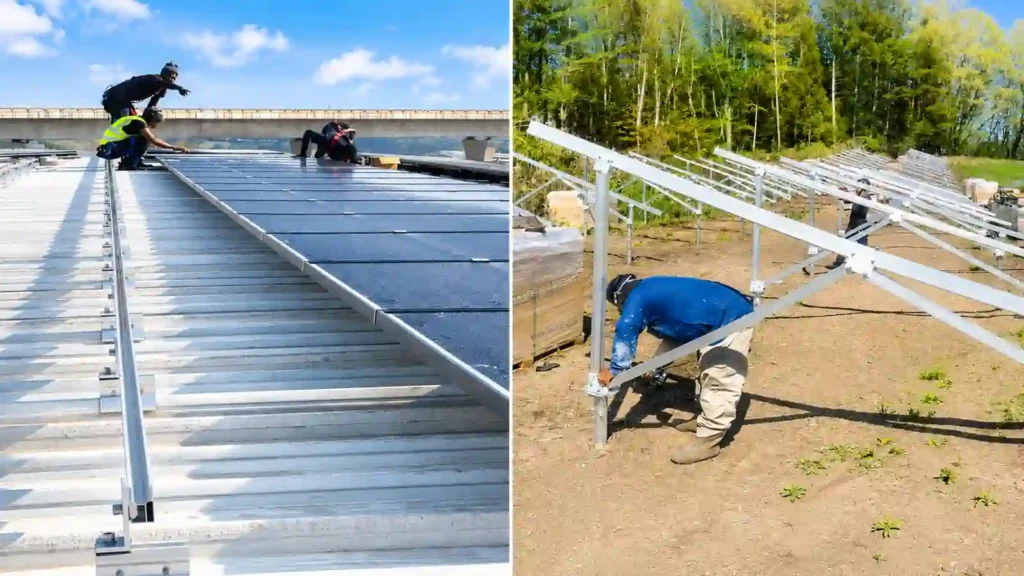
A structurally suitable roof can make use of space that is already available.
A ground-mounted project may offer more freedom in array layout, tilt, row spacing, and maintenance access.
There is no universal answer to which one is better.
The correct choice depends on the real project conditions.
How Do You Choose the Right Solar Mounting System?
A reliable mounting-system selection starts with project inputs rather than a catalog part number.
Before the mounting structure is finalized, the following information should normally be reviewed.
1. Installation Surface
Identify whether the project is installed on:
- Metal roof
- Tile roof
- Shingle roof
- Flat roof
- Open ground
- Parking area
- Agricultural land
- Balcony
- Another supporting structure
This determines the first level of system selection.
2. PV Module Dimensions
Provide:
- Framed or frameless
- Module length
- Width
- Frame thickness
- Weight
- Mounting-hole information where relevant
Large-format modules can affect rail span, clamp position, structural spacing, and handling.
3. Module Quantity and Array Layout
The mounting supplier should understand:
- Module quantity
- Portrait or landscape orientation
- Modules per row
- Number of rows
- Row length
- Available installation area
A change in the module layout can change the mounting BOM.
4. Wind Conditions
Wind can create pressure, uplift, and lateral forces.
The project should provide the applicable design wind information where available. The strength of the solar mount bracket needs to be calculated based on the wind speed.
5. Snow Conditions
Snow adds gravity load and may accumulate differently depending on roof shape, array geometry, and surrounding structures. The strength of the solar mount bracket needs to be calculated based on the snow load. And the snow load determines the minimum ground clearance, the minimum ground clearance of the ground solar mount must be no less than the accumulated snow depth. Otherwise, the ground pv mounting system would be covered and submerged by accumulated snow.
6. Tilt Angle
The required tilt can affect:
- Triangle-frame geometry
- Ground structure height
- GL
- Wind exposure
- Row spacing
- Braces
- Structural members
- Shading
7. Roof Structure or Foundation Conditions
Roof projects may need information about rafters, purlins, deck, structural steel, or other load-bearing elements.
Ground projects may require soil information, pile tests, geotechnical data, or foundation assumptions.
8. Corrosion Environment
Projects near the coast, heavy industry, or other corrosive environments may need additional material and surface-treatment considerations.
9. Clearance and Access
Different projects may require clearance for:
- Roof maintenance
- Vegetation
- Vehicles
- Farm machinery
- Workers
- Livestock
- Drainage
- Electrical equipment
10. Installation Method
The mounting design should also consider:
- Whether roof penetration is acceptable
- Available installation tools
- Foundation construction equipment
- Pre-assembly
- Shipping restrictions
- Installation sequence
For preliminary planning, the Solar Mounting System Calculator can help organize basic system and project inputs before detailed engineering review.
What Materials Are Used in Solar Mounting Systems?
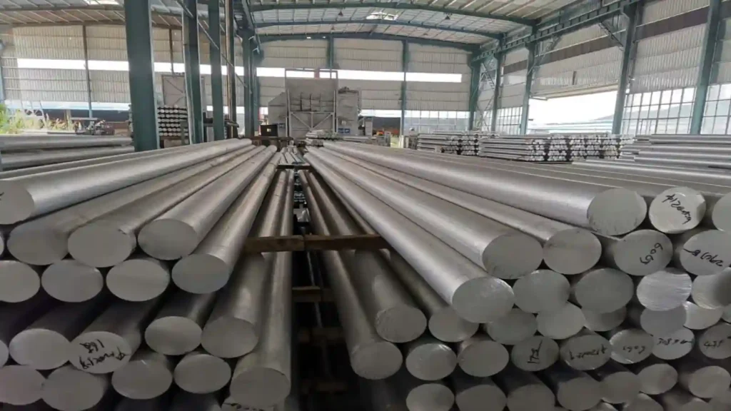
Solar mounting structures are commonly manufactured from aluminum, galvanized or coated steel, and stainless-steel hardware.
Each material is suited to different parts of the system.
Aluminum
Extruded aluminum is widely used for:
- Solar rails
- Module clamps
- Roof brackets
- Beams and profiles
- Rail connectors
Its relatively low weight, corrosion resistance, and ability to be extruded into detailed profiles make it useful for many PV mounting applications.
Galvanized Steel/ZAM
Steel is commonly used where larger structural members or higher stiffness are required.
Applications may include:
- Ground posts
- Driven piles
- Carport columns
- Main beams
- Agrivoltaic structures
- Braces
- Foundation interfaces
The coating or galvanizing specification should be selected according to the project requirements and installation environment.
Stainless Steel
Stainless steel is frequently used for:
- Bolts
- Nuts
- Washers
- Roof hooks
- Clips, ground lugs
- Connection hardware
The complete connection should be reviewed rather than assuming that any stainless-steel fastener is suitable for every environment or mating material.
Manufacturing quality also matters.
Dimensions, profile geometry, drilling, punching, surface treatment, component matching, and final packaging all influence whether a mounting system arrives ready for efficient project installation.
More information about these processes is available under Factory Capability and Quality Control.
How Do Wind and Snow Loads Affect Solar Racking?
Wind and snow can affect almost every structural level of a solar mounting system.
Wind may create:
- Uplift
- Downward pressure
- Lateral forces
- Torsional effects
- Higher reactions at edge or corner zones
Snow adds vertical load and can create uneven accumulation in some layouts.
These loads can affect:
- Rail size& rail thickness
- Allowable rail span
- Roof attachment spacing
- Ballast quantity
- Column spacing
- Beam dimensions
- Braces type
- Ground foundation reactions
- Pile pull-out requirements
- Module clamp positions
- Carport structure
- Agrivoltaic frame height and stability
This is why a single wind or snow value should not be applied universally to every solar racking project.
The appropriate structural design depends on project location, applicable standards, terrain or exposure, array geometry, roof or soil conditions, module dimensions, and the supporting structure.
Rail-Based, Shared-Rail, and Railless Solar Mounting
Rooftop PV mounting systems are often described as rail-based or railless.
A third configuration, shared-rail mounting, is also useful to understand.
Rail-Based Solar Mounting
Rail-based systems use continuous or sectional mounting rails between the roof attachments and modules.
Advantages can include:
- Flexible module alignment
- Familiar mid- and end-clamp interface
- Easier row adjustment
- Defined rail splice points
- Convenient cable-management interfaces
Rail-based systems remain widely used across different roof applications.
Shared-Rail Solar Mounting
Shared-rail systems reduce the number of rail lines by allowing compatible module positions to share selected rails.
This can reduce rail quantity in suitable layouts.
However, module orientation, clamp zones, attachment spacing, structural span, and the system’s installation rules still need to be followed.
Railless Solar Mounting
Railless systems reduce or eliminate continuous long rails.
They may use:
- Direct attachments
- Compact mounts
- mini rails
- Short structural profiles
- System-specific brackets
Potential advantages include less long-material handling and a low-profile installation.
However, compatibility with the module frame, roof profile, attachment pattern, and structural design remains critical.
| System | Main Interface | Typical Advantage | Important Checks |
|---|---|---|---|
| Rail-Based | Continuous or sectional rail | Flexible alignment | Span, splice, clamps, attachments |
| Shared-Rail | Reduced shared rail lines | Lower rail quantity in suitable layouts | Module orientation and system rules |
| Railless | Compact or direct mounts | Reduced long-rail handling | Roof profile, module, attachments, loads |
No approach is universally better.
The right system depends on the actual roof and project configuration.
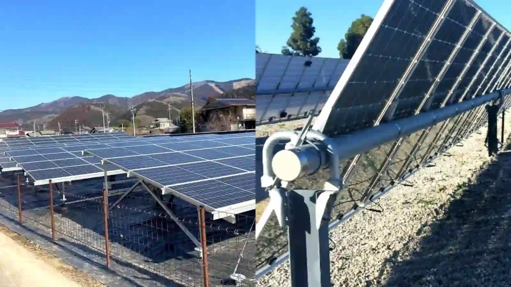
Fixed-Tilt vs Tracking Solar Racking
Ground-mounted PV systems can use either stationary fixed-tilt structures or tracking structures.
Both support solar modules, but their structural and mechanical complexity is very different.
Fixed-Tilt Solar Racking
A fixed-tilt system holds modules at a predetermined angle.
A typical structure may use:
- Foundations
- Posts
- Bases
- Beams
- Braces
- Rails or purlins
- Module clamps
There is no daily tracking movement.
Fixed mounting is used for many commercial, distributed, and utility ground-mounted projects.
Tracking Solar Racking
A tracking system changes module orientation during the day.
Depending on the design, it may include:
- Torque tubes
- Bearings
- Drive systems
- Motors or actuators
- Controllers
- Rotating module rows
Tracking can increase energy capture in suitable projects, but it also introduces additional mechanical components, maintenance requirements, foundation considerations, and control systems.
This guide focuses primarily on stationary mounting systems such as roof racking, fixed tilt ground mount solar racking, solar carports, and agrivoltaic structures.
How Does a Solar Mounting Project Move from Design to Installation?
For B2B projects, mounting-system work normally begins before manufacturing.
A practical project process can be divided into several stages.
| Stage | Main Work | Typical Output |
|---|---|---|
| 1. Project Information | Collect module, site, roof, soil, wind, snow, and layout information, tilt angel | Project input data |
| 2. System Selection | Select roof attachment, foundation, structural concept, and component family | Preliminary configuration |
| 3. Structural Layout | Define rails, spans, columns, beams, tilt, clearance, and connections | Engineering layout |
| 4. Component Matching | Confirm rails, clamps, brackets, fasteners, grounding, foundations | Project BOM |
| 5. Production | Cut, drill, punch, fabricate, and prepare components | Production parts |
| 6. Inspection | Check dimensions, quantities, finishes, and matching | QC / release |
| 7. Packing & Delivery | Group and label parts for shipment | Project packages |
| 8. Installation | Assemble the approved mounting configuration | Installed structure |
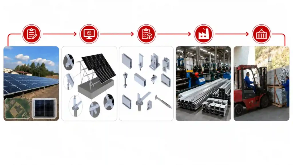
This workflow is particularly important when the module model or layout changes after an initial design.
If module dimensions, frame thickness, quantity, or row arrangement change, the rails, clamps, attachments, splices, foundations, and fastener quantities may also change.
Production should therefore follow the confirmed project drawing and final BOM rather than an earlier preliminary version.
Common Solar Mounting Mistakes to Avoid
Using the Same Attachment for Every Roof Type
Metal roofs, tile roofs, flat roofs, and shingle roofs have different mechanical and waterproofing interfaces.
An attachment designed for one roof type should not automatically be used for another.
Ignoring Module Frame and Clamp Compatibility
The clamp should be compatible with the module frame and mounting rail.
Module changes should trigger a compatibility review before production.
Selecting Rail Span Without Reviewing the Full Load Path
Rail span depends on more than the rail itself.
Module loads, wind, snow, attachment spacing, and structural support all influence the required configuration.
Underestimating Roof Waterproofing
When a roof installation includes penetrations, the attachment and sealing method should be coordinated with the roof material and structure.
Choosing a Foundation Before Reviewing Soil Conditions
Ground screws, driven piles, and concrete foundations have different use cases.
The correct foundation depends on site conditions, soil performance, construction equipment, structural reactions, and project requirements.
Continuing with a Preliminary BOM After the Project Changes
Module or layout changes can alter component quantities.
The final order should always follow the confirmed project configuration.
What Information Does a Solar Mounting Supplier Need?
Providing complete project information can reduce repeated clarification and make mounting selection more efficient.
For most professional projects, useful information includes:
- Project country and location
- PV module datasheet
- Module dimensions
- Module frame thickness
- Module quantity
- Proposed array layout
- Roof type or site information
- Roof profile where applicable
- Soil information for ground projects
- Foundation requirement information for ground projects
- Wind design requirements
- Snow design requirements
- Required tilt
- Module orientation
- Ground clearance
- Parking layout for carports
- Agricultural clearance for agrivoltaics
- Available CAD drawings
- Roof drawings
- Site photos
- Survey information
- Required delivery scope
- Project schedule
The more complete the inputs are, the easier it becomes to move from a general product discussion to a project-specific mounting solution.
Explore Related Solar Mounting Systems
If you already know the installation type, continue with the relevant product section:
- Roof Solar Mounting Systems — mounting for metal, tile, pitched, shingle, and flat roofs.
- Ground Solar Mounting Systems — fixed structures and multiple foundation options for open-field PV.
- Solar Carport Mounting System — structural PV canopies for parking areas.
- Agrivoltaic PV Mounting System — high-clearance mounting for agricultural land.
- Balcony Solar Mounting System — compact PV mounting for suitable balconies and railings.
- Solar Mounting Accessories — rails, clamps, brackets, fasteners, grounding parts, and related mounting hardware.
Common Questions About Solar Racking
Is solar racking the same as a solar mounting system?
In most project discussions, yes.
Solar racking system, solar mounting system, PV mounting system, and solar mounting structure are commonly used for the structural system that supports and secures photovoltaic modules.
Terminology may vary between manufacturers and markets.
What are the main types of solar mounting systems?
The major categories include roof-mounted systems, ground-mounted systems, solar carports, agrivoltaic structures, and balcony mounting systems.
Each category can be divided further according to roof type, foundation method, tilt, and structural configuration.
What is solar racking made of?
Common materials include aluminum profiles, galvanized steel structural and stainless-steel bolt&connection hardware.
The correct material depends on the mounting system, structural requirements, and installation environment.
How are solar panels attached to racking?
Framed PV modules are commonly secured with mid clamps and end clamps on compatible rails or support profiles.
Some systems use short rails, direct mounting points, or other system-specific fixing methods.
Does solar racking need grounding or bonding?
Metallic mounting systems may require grounding or bonding according to the electrical design, mounting configuration, and applicable project requirements.
Grounding clips, lugs, and bonding hardware may be incorporated into the system.
How do I choose between roof and ground mounting?
Consider available roof or land area, roof structural suitability, soil conditions, foundation requirements, desired tilt, maintenance access, and overall project constraints.
Neither option is universally better.
What affects the required strength of solar racking?
Important factors include module dimensions and weight, wind, snow, tilt angel, rail span, attachment spacing, column spacing, structural geometry, profile’s thickness, roof or foundation conditions, and applicable design requirements.
What is the difference between fixed-tilt and tracking solar racking?
Fixed-tilt systems keep modules at a constant angle.
Tracking systems rotate the module rows during the day and require additional mechanical and control components.
What information is needed to design a solar mounting system?
Start with project location, module datasheet, module quantity, array layout, installation surface, roof or soil information, wind and snow requirements, tilt angle, orientation, clearance requirements, and any available drawings or site photos.
Need a Solar Mounting System for a Real Project?
Send Easy Solar your PV module information, project layout, roof or ground conditions, wind and snow requirements, tilt angel and available project drawings.
Our team can review the mounting configuration and help prepare a project-based solution.
Explore Solar Mounting Systems
References & Technical Sources
- U.S. Department of Energy — Solar Photovoltaic System Design Basics
https://www.energy.gov/cmei/systems/solar-photovoltaic-system-design-basics - U.S. Department of Energy — Solar Photovoltaic Manufacturing Basics
https://www.energy.gov/cmei/systems/solar-photovoltaic-manufacturing-basics - U.S. Department of Energy — Life Cycle of Photovoltaic Systems: Install and Commission a Photovoltaic System
https://www.energy.gov/cmei/femp/life-cycle-photovoltaic-systems-install-and-commission-photovoltaic-system - U.S. Department of Energy — Severe Weather Resilience in Solar Photovoltaic System Design
https://www.energy.gov/cmei/femp/severe-weather-resilience-solar-photovoltaic-system-design - Penn State University — PV Systems Mounting Types
https://courses.ems.psu.edu/ae868/node/913

Sales Manager at Easy Solar Solar Mounting Systems. With over 1o years of experience in the solar industry, I specialize in providing reliable andcost-effective mounting solutions for distributors, installers, and EPC companies. Experienced in intemational sales and commited to building long-term partnerships worldwide.