How to Choose a Solar Mounting System for a PV Project
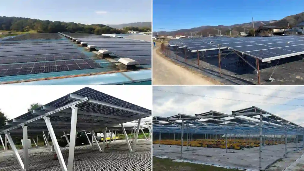
Choosing a solar mounting system should not begin with a rail profile, bracket catalog, or material preference.
It should begin with the project.
A mounting system has to fit the installation surface, transfer wind and snow loads safely, match the PV module, preserve roof or ground conditions, tolerate the local environment, support an efficient installation workflow, and remain practical to inspect and maintain over the project life.
That is why two projects using the same PV module can require completely different mounting systems.
A warehouse with a standing seam metal roof may favor non-penetrating seam clamps. A membrane flat roof may need a ballasted, mechanically attached, or hybrid system depending on roof capacity and wind. An open-field project may use driven piles, ground screws, or concrete foundations depending on soil. A parking project may justify a solar carport because the structure also provides shade and protected parking.
DOE likewise treats PV mounting as a site- and system-specific design decision: mounting structures must remain stable and durable while resisting environmental exposure, and ground-mounted systems may use fixed structures or tracking depending on project requirements.
The right question is not:
“Which solar mounting system is best?”
It is:
“Which mounting system best fits this project’s site, loads, module, installation constraints, and lifecycle requirements?”
If you first want to understand how the physical mounting chain works, read How Are Solar Panels Mounted?. For the main mounting categories, see Types of Solar Mounting Systems.
For commercial product options, explore Solar Mounting Systems.
Solar Mounting System Selection at a Glance
| Project Condition | Mounting Systems to Evaluate First | Critical Selection Questions |
|---|---|---|
| Pitched roof | Rail-based, mini-rail, or roof direct attach | Roof material, structural support, waterproofing, roof slope, attachment spacing |
| Standing seam metal roof | Seam clamp with rail, mini rail, or direct attach | Exact seam geometry, clamp compatibility, load capacity, module support method |
| Trapezoidal / corrugated metal roof | L feet, profile brackets, hanger bolts, mini rails | Rib geometry, purlin location, sealing, fastener connection, corrosion |
| Flat roof | Ballasted, triangle solar mount, concrete foundation solar rack | Roof load capacity, membrane, wind, penetrations, drainage, maintenance |
| Low-slope metal roof | Triangle solar mount, adjustable solar mounting, mini rail, L feet or seam clamp | Roof load capacity, membrane, wind, penetrations, drainage, maintenance |
| Open land | Fixed-tilt ground mount, ballasted, triangle solar rack or tracker | Soil, foundation, terrain, energy model, wind, snow, access |
| Parking area | Solar carport | Foundation, column layout, vehicle clearance, drainage, span, collision protection |
| Agricultural land | Agrivoltaic mounting or ground mounting system | Crop or livestock use, equipment clearance, row spacing, structure height, foundation |
| Balcony / small façade edge | Balcony mounting | Guardrail or wall structure, module size, wind, local restrictions, fall protection |
This table is a shortlist, not a final specification.
The final system should pass a series of project-specific checks before components are released for production or installation.
Use a Two-Stage Selection Process: Eliminate First, Optimize Second
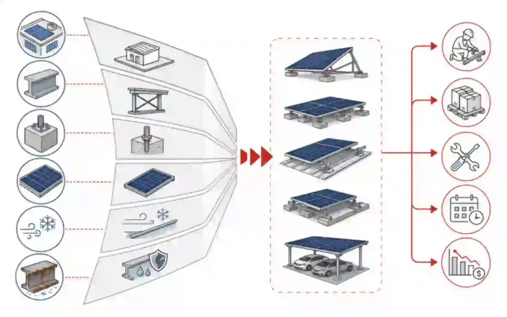
One reason mounting-system selection becomes confusing is that project teams often compare every option at the same time.
A more useful approach is to separate the decision into two stages.
Stage 1: Eliminate Systems That Do Not Fit the Project
These are must-pass constraints.
Examples include:
- The roof cannot accept the required ballast weight.
- The owner does not allow new roof penetrations.
- The standing seam geometry is incompatible with the proposed seam clamp.
- The soil cannot support the preferred ground foundation without major remediation.
- The project wind or snow reactions exceed the selected structural configuration.
- The module mounting zone is incompatible with the support spacing.
- Vehicle clearance makes a proposed carport geometry impractical.
- The site corrosion environment requires materials or finishes not available in the proposed system.
A system that fails a must-pass constraint should normally be removed from the shortlist before price comparison.
DOE’s current PV procurement guidance follows a similar project-first logic: project validation should screen site conditions, available space, system type, weather hazards, access, construction logistics and regulatory constraints before the technical specification and procurement process is finalized.
Stage 2: Optimize the Remaining Systems
Once the technically unsuitable options are eliminated, compare the remaining systems using optimization factors such as:
- Installed cost
- Installation speed
- Material quantity
- Shipping volume
- Pre-assembly
- Roof or land utilization
- Energy yield
- Maintenance access
- Replaceability
- Future roof work
- Foundation removability
- Project schedule
- Long-term inspection effort
This two-stage method prevents a low hardware price from keeping an unsuitable mounting concept in the decision process.
Step 1: Identify the Installation Surface and Available Space
The first decision is where the PV modules will be installed.
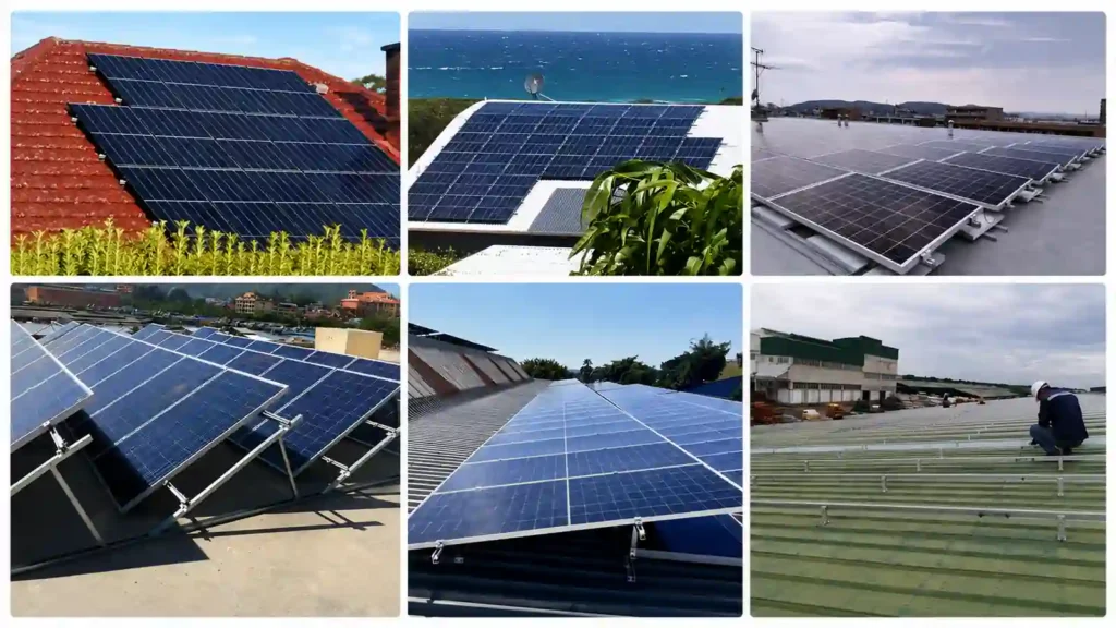
Roof
A roof mount uses an existing building as part of the structural support system.
This can reduce land use, but the project must work with the roof that already exists.
Check:
- Roof material
- Roof slope
- Roof age
- Roof condition
- Structural support
- Rafter, purlin, joist, or deck spacing
- Roof membrane or covering
- Drainage
- Equipment and access zones
- Roof warranty
- Available unshaded area
PNNL recommends selecting rooftop mounting around roof type, roof slope, weatherproofing, installation practicality, module compatibility, and wind and snow loading rather than using one universal roof attachment method.
For roof projects, see Roof Solar Mounting Systems.
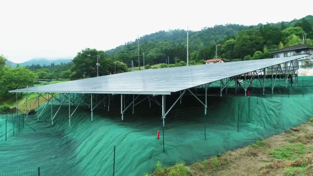
Ground
A ground-mounted system creates its own structural frame and foundation.
This provides more freedom in tilt, orientation, row spacing, table dimensions, and maintenance access, but introduces soil, foundation, civil, drainage, and land-use questions.
Check:
- Available land
- Topography
- Soil / geotechnical conditions
- Groundwater
- Frost
- Drainage
- Flood exposure
- Access roads
- Vegetation
- Foundation installation equipment
- Land-use restrictions
DOE’s current installation guidance specifically identifies foundation, topography and soil as ground-mounted PV considerations.
For ground projects, see Ground Solar Mounting Systems.
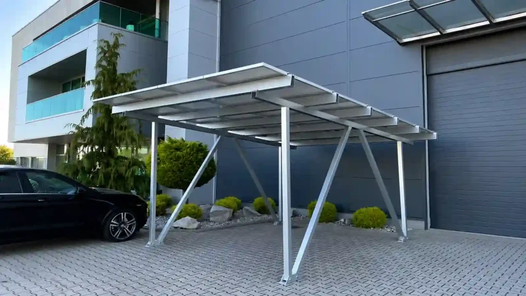
Carport
A solar carport turns parking space into both a PV site and a canopy.
The mounting system must therefore solve more than module support.
Check:
- Vehicle clearance
- Column locations
- Parking-bay layout
- Foundation conditions
- Span
- Drainage
- Lighting or EV charging integration
- Collision protection
- Maintenance access
DOE’s current PV project screening guidance also treats carports separately, including fire access, vehicle height and collision-protection considerations.
See Solar Carport Mounting System.
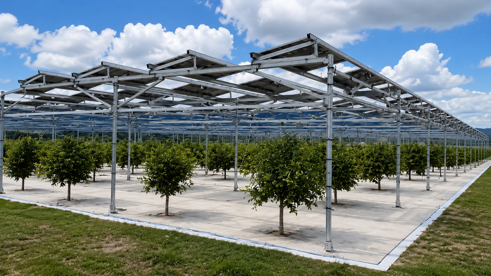
Agrivoltaic
Agrivoltaic mounting adds an agricultural operating requirement to the PV structure.
The structure may need to preserve:
- Tractor or equipment clearance
- Crop access
- Livestock movement
- Agricultural row spacing
- Water management
- Farm-road access
- Elevated cable routing
- Long-term flexibility of land use
See Agrivoltaic PV Mounting System.
The first selection should therefore be based on site use, not just panel orientation.
Step 2: Confirm the Structural Support Before Choosing Hardware
Once the installation type is known, identify what ultimately carries the PV loads.
For rooftop projects, the final support may be:
- Timber rafters
- Steel purlins
- Structural deck
- Concrete slab
- Standing seam roof system
- Other engineered building members
For ground projects, it may be:
- Driven pile
- Ground screw
- Concrete foundation
- Ballast
- Other project-specific foundation
For carports, the lower load path can include:
Module → Purlin / Rail → Beam → Column → Base Plate / Anchor → Foundation → Soil
The mounting system should be selected around that load path.
Do not assume that a roof sheet, roof tile, or visible fastener is automatically the final structural support.
PNNL specifically recommends tying rooftop mounting attachments into structural members and notes that concentrated mounting loads must be considered at rafters, joists, decking or other building elements.
Do not assume that one ground foundation can be used across every soil condition.
A technically suitable system should have a clear answer to:
Where do the module loads go next?
If that answer is uncertain, the mounting selection is not complete.
Step 3: Decide the Attachment or Foundation Strategy
The primary attachment often determines the rest of the system.
Pitched and Metal Roofs
Possible attachment methods include:
- Roof hooks
- L feet
- Hanger bolts
- Flashed anchors
- Trapezoidal brackets
- Mini brackets
- Triangle solar racking system
- Standing seam clamps
- Adjustable solar panel mount
The right choice depends on roof geometry, structural support, waterproofing, penetration restrictions, and project loads.
PNNL emphasizes that roof penetrations should be appropriately flashed and sealed and that the anchoring system must be compatible with the roof and PV module.
Flat Roofs
The main choices are often:
- Ballasted
- Triangle solar racking system
- Concrete foundation solar mount
- Mechanically attached
- Hybrid
A fully ballasted system can reduce penetrations, but it adds dead load.
A mechanically attached system reduces dependence on ballast but requires structural attachment and waterproofing details.
A hybrid system can combine both methods where project conditions vary by roof zone or ballast weight needs to be reduced.
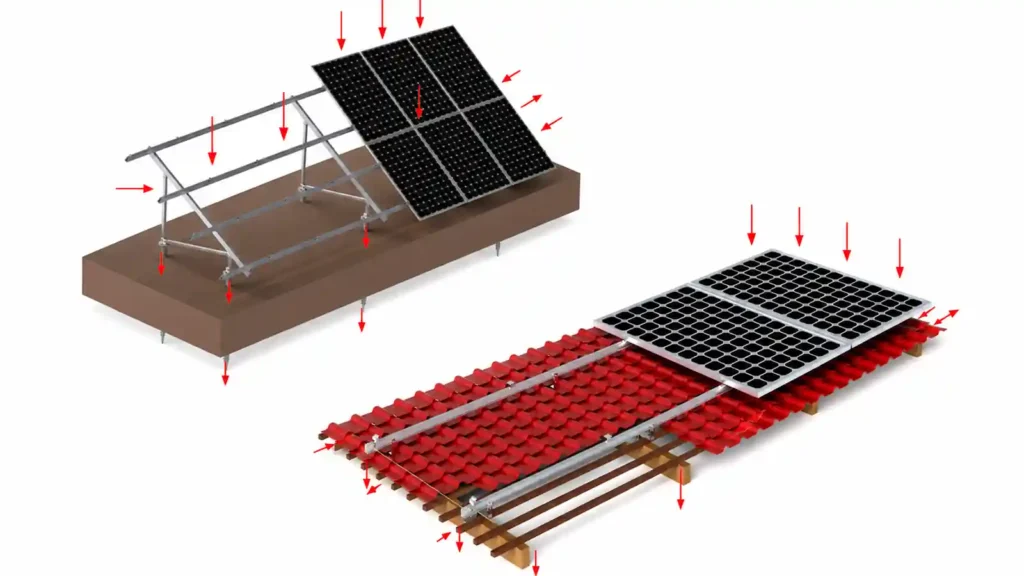
DOE’s severe-weather guidance recommends strategic mechanical attachment rather than relying only on fully ballasted rooftop PV in high-wind conditions.
Ground Mounts
Typical foundation families include:
- Driven piles
- Ground screws
- Concrete blocks
- Ballasted foundations
Foundation selection should follow soil and structural reactions rather than habit.
The mounting-system decision is therefore partly an attachment decision and, for ground arrays, partly a geotechnical decision.
Step 4: Confirm the Final PV Module Before Finalizing the Racking
The module is not independent from the mounting system.
Confirm:
- Module manufacturer and model
- Framed or frameless
- Length
- Width
- Frame thickness
- Weight
- Approved clamp zones
- Approved mounting holes
- Portrait or landscape orientation
- Module quantity
- Modules per row or table
These inputs affect:
- Rail or purlin spacing
- Clamp type
- Clamp position
- Table dimensions
- Row length
- Attachment spacing
- Structural reactions
- Bill of materials
Large-format modules can change the mounting layout significantly compared with smaller modules.
If the module changes after the mounting design is complete, the system should be reviewed again before production.
A previous BOM should not automatically be reused. The solar mounting system design and BOM are required to update based on the latest conditions.
PNNL similarly recommends verifying compatibility between the selected PV modules and the chosen mounting system using the relevant manufacturer documentation.
Step 5: Separate Energy-Geometry Decisions from Structural Decisions
Tilt and orientation affect energy production, but they also affect structure.
For fixed systems, check:
- Tilt angle
- Azimuth
- Portrait or landscape orientation
- Row spacing
- Shading
- Roof slope
- Ground clearance
- Snow shedding
- Wind exposure
For ground-mounted projects, also consider whether fixed tilt or tracking is appropriate.
DOE notes that fixed structures establish module tilt and orientation, while tracking systems can increase ground-mounted energy production but add cost and maintenance requirements.
For flat roofs, a low-tilt east-west layout may serve a different project objective from a higher-tilt south-facing layout.
For agrivoltaic projects, energy optimization must be coordinated with farm operations and clearance.
A useful rule is:
Do not optimize tilt or array density in isolation from the mounting structure.
An energy model may identify an attractive geometry, but the final arrangement still needs a practical structure, foundation or roof attachment, access route, drainage plan, and construction method.
Step 6: Design for Wind and Snow Before Comparing Component Price
Wind and snow can change almost every part of a mounting system.
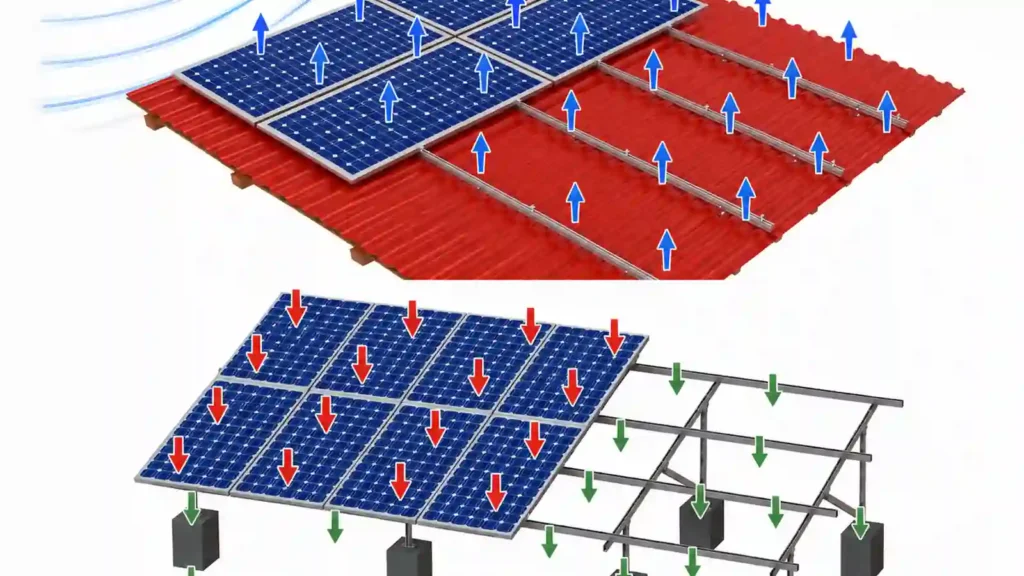
Wind can affect:
- Module loads
- Clamp loads
- Rail or purlin span
- Attachment spacing
- Bracing
- Post reactions
- Foundation uplift
- Roof ballast
- Edge and corner zones
- Tracker stow strategy
Snow can affect:
- Downward module loading
- Rail and beam span
- Support spacing
- Bracing
- Ground clearance
- Foundation reactions
- Roof capacity
- Snow accumulation below modules
DOE recommends that racking and frame systems be engineered for turbulent wind forces, with appropriate bracing and critical fastened joints designed for the actual loading conditions.
This is why a mounting system should not be selected from a generic statement such as “rated for high wind.”
The relevant question is whether the proposed configuration has been designed for the actual project conditions.
For procurement, request project-specific structural inputs or calculations appropriate to the project rather than relying on one marketing load number.
Step 7: Match Materials and Finishes to the Corrosion Environment
Material selection is often simplified into “aluminum versus steel.”
The real decision is more detailed.
A mounting system can combine:
- Aluminum rails
- Galvanized steel or aluminum posts
- Galvanized steel or aluminum beams
- Stainless-steel bolt & aluminum fasteners
- Aluminum module clamps
- Aluminum base
- Grounding components
- EPDM or other sealing materials
The combination must remain suitable in the actual environment.
Corrosion risk is more important in:
- Coastal sites
- Marine-adjacent projects
- Industrial locations
- Agricultural environments
- High-humidity areas
- Sites with corrosive dust or gases
- Aggressive soils
- Locations with recurring salt exposure
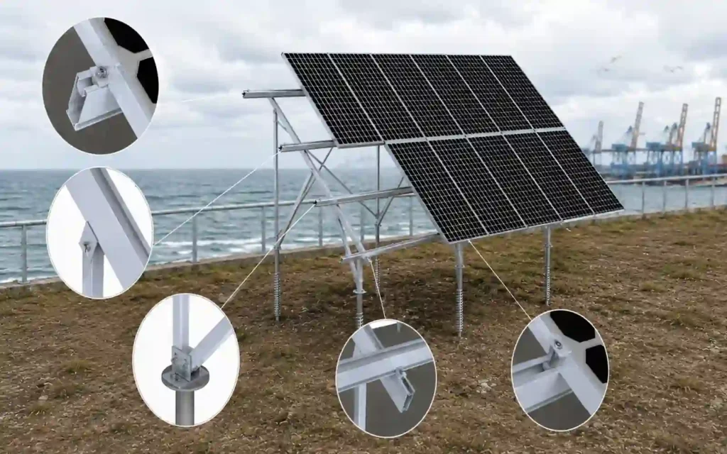
DOE identifies module frames, fasteners and racking systems as components vulnerable to corrosion and highlights oxidation, galvanic corrosion and crevice corrosion as important PV-system risks, particularly where dissimilar metals are combined.
Check:
- Base material
- Anodizing thickness
- Galvanizing thickness
- Fastener grade
- Dissimilar metal contact
- Cut edges
- Installation damage
- Soil exposure
- Drainage and trapped moisture
- Maintenance requirements
The lightest or cheapest material is not automatically the best lifecycle choice.
The system should match both the structural demand and the environmental exposure.
Step 8: Compare Installation Method and Tolerance
A good design still has to be buildable.
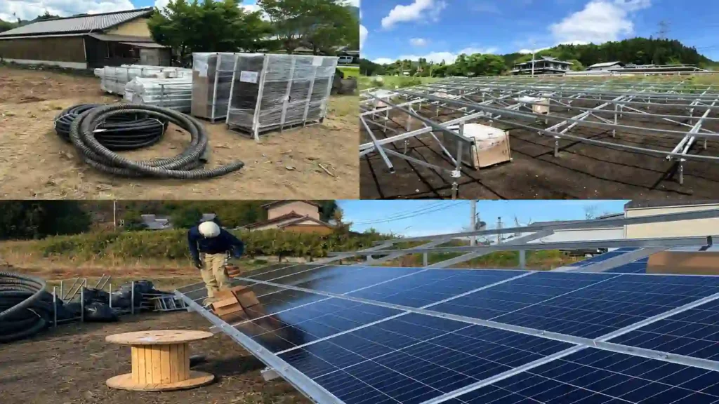
Evaluate:
- Number of unique components
- Pre-assembly
- Field drilling
- Long-rail handling
- Rail splices
- Fastener count
- Adjustment range
- Foundation tolerances
- Roof attachment layout
- Module alignment process
- Required tools
- Torque-control requirements
- Crane or lifting requirements
- Ballast handling
- Pile-driving or screw-driving equipment
- Working-at-height requirements
Two systems can use similar quantities of aluminum or steel but produce very different labor requirements.
DOE’s procurement guidance specifically recommends considering construction logistics, site access, system-specific conditions and technical specifications before project award.
For export projects, also consider:
- Packing material
- Packing density
- Packaging waste disposal issues and costs
- Pallet dimensions
- Container utilization
- Component labeling
- BOM organization
- Installation sequence
- Spare parts
Installation efficiency should be evaluated together with material cost.
Step 9: Check Maintenance Access Before Increasing Array Density
The highest possible module count is not always the best system layout.
The completed PV system still needs inspection, cleaning, repair, cable work, roof maintenance, vegetation management, and module replacement.
Rooftops
Maintain access to:
- Roof drains
- Hatches
- HVAC equipment
- Walkways
- Fire / service routes
- Membrane inspection areas
- Roof edges where required
Ground Mounts
Maintain access for:
- Vegetation control
- Drainage inspection
- Module replacement
- String / cable maintenance
- Foundation inspection
- Site roads
- Snow management where relevant
Carports
Maintain:
- Vehicle access
- Driver sight lines
- Drainage
- Column protection
- Electrical equipment access
- Lighting / EV charging access
DOE recommends planning O&M during system design and providing adequate access and clearance around equipment rather than treating maintenance as an afterthought.
The mounting system should help the site remain usable after commissioning.
Step 10: Consider the Project Lifecycle, Not Only Installation Day
The mounting system may remain in service for decades.
Selection should therefore include future events.
Ask:
- Will the roof need replacement before the PV array reaches end of life?
- Can modules be removed and reinstalled without destroying the racking?
- Can ballast be returned to the correct locations after roof work?
- Can corroded or damaged fasteners be replaced?
- Are spare clamps and hardware available?
- Can cable routes be accessed?
- Can a ground foundation be removed at the end of the project if required?
- Can a carport be repaired after vehicle impact?
- Can an agrivoltaic structure adapt to future farm operations?
DOE’s 2026 procurement guidance explicitly frames PV decisions around a long project life and recommends preparing O&M planning during the design and procurement stage.
A system with a low first cost can become expensive if every roof repair or component replacement requires large-scale disassembly.
Step 11: Compare Total Installed and Lifecycle Cost, Not Hardware Price Alone
The mounting hardware price is only one part of project cost.
A fair comparison can include:
- Racking material
- Foundations or roof attachments
- Fasteners
- Ballast
- Freight
- Packing
- Equipment
- Installation labor
- Pre-assembly
- Structural engineering
- Roof waterproofing
- Civil work
- Testing
- Rework risk
- Commissioning
- O&M
- Future roof work
- Spare parts
- End-of-life removal where applicable
For example, a system that uses less aluminum but requires more rooftop drilling may not have the lowest installed cost.
A ground screw may cost more than a simple steel pile as an individual component but may be attractive if it reduces another part of the civil scope at a suitable site.
A ballasted roof system may reduce penetration work but create more lifting and roof-load constraints.
The objective is not the lowest component price.
It is the best project outcome at an acceptable lifecycle cost.
DOE’s procurement process similarly recommends evaluating capital cost, O&M, site conditions and lifecycle economics rather than selecting equipment only from its purchase price.
Step 12: Verify the Engineering and Documentation Package
Before placing an order, confirm what technical information accompanies the mounting system.
Depending on the project, useful deliverables can include:
- General arrangement drawing
- Structural layout
- Attachment or foundation layout
- Component drawings
- Module compatibility
- Bill of materials
- Fastener specification
- Material and finish information
- Installation manual
- Torque requirements
- Grounding / bonding details
- Waterproofing details
- Packing list
- Quality documentation
- Project-specific structural information
- Inspection requirements
DOE’s current technical-specification framework emphasizes carrying technical requirements through procurement documents, design drawings, submittal review, equipment delivery, commissioning and verification.
The exact documents vary by project size and market.
The important point is that the selected system should be understandable and buildable from the supplied technical package.
A mounting system should not depend on installers guessing where components go.
A Practical Selection Scorecard
Once unsuitable systems have been eliminated, the remaining options can be compared using a simple project scorecard.
| Selection Area | Questions to Ask | Must-Pass or Optimize? |
|---|---|---|
| Site / Roof Fit | Does the system physically suit the site or roof? | Must-pass |
| Structural Support | Is the load path defined and acceptable? | Must-pass |
| Wind / Snow | Can the configuration meet project loads? | Must-pass |
| Module Compatibility | Does it match module dimensions and mounting zones? | Must-pass |
| Waterproofing / Foundation | Is the attachment or foundation strategy acceptable? | Must-pass |
| Corrosion | Are materials and finishes suitable for the environment? | Must-pass |
| Installation | Can the project be installed with available labor and equipment? | Optimize |
| Logistics | Is packing, handling and delivery practical? | Optimize |
| Maintenance | Can the array be inspected and repaired efficiently? | Optimize |
| Lifecycle | Does it fit roof replacement / land-use / removal plans? | Optimize |
| Cost | What is the installed and lifecycle cost? | Optimize |
| Documentation | Are drawings, BOM and installation requirements complete? | Must-pass / Optimize |
This framework is more useful than choosing a mounting system from a single product feature.
Example 1: Standing Seam Commercial Warehouse
Suppose a project has:
- Standing seam metal roof
- Suitable roof condition
- No new penetrations preferred
- Large framed modules
- Moderate-to-high wind exposure
The first system to evaluate may be a compatible standing seam clamp system.
But the selection is not complete until the project checks:
- Exact seam profile
- Clamp compatibility
- Required holding capacity
- Clamp spacing
- Rail or direct-attach architecture
- Module mounting zone
- Wind-zone requirements
- Roof warranty
- Cable support
- Corrosion environment
The phrase “non-penetrating” alone is not enough to approve the system.
Example 2: Large Commercial Flat Roof
Suppose a project has:
- Single-ply membrane roof
- Limited reserve roof capacity
- High wind exposure
- Roof penetrations permitted only at selected locations
A fully ballasted system may create too much dead load.
A fully mechanically attached system may create more penetrations than preferred.
A hybrid system may therefore be worth evaluating.
The decision should compare:
- Ballast weight
- Attachment reactions
- Roof membrane detail
- Wind zones
- Drainage
- Access
- Installation logistics
- Future roof work
DOE’s high-wind guidance is one reason this comparison should be made structurally rather than assuming a fully ballasted arrangement is always preferable.
The best option is the one that solves the complete roof problem.
Example 3: Open-Field Fixed-Tilt Project
Suppose a project has:
- Open land
- Fixed-tilt array
- Variable soil
- Moderate terrain slope
- Large module quantity
The correct selection should begin with:
- Topographic survey
- Geotechnical information
- Foundation reactions
- Pile / ground screw / concrete constructability
- Wind and snow
- Table geometry
- Module orientation
- Installation equipment
- Corrosion
- Drainage
DOE explicitly includes foundation, soil, topography, wet-soil conditions and weather exposure in ground-mounted PV planning.
Do not choose the foundation from component price before reviewing the site.
Common Mistakes When Choosing a Solar Mounting System
Choosing by Product Category Alone
“Metal roof,” “ground mount,” or “flat roof” is only the first level of selection.
The project still needs a specific attachment, structural configuration, material, and layout.
Choosing the Cheapest Hardware Before Structural Review
Low component cost cannot compensate for an unsuitable load path.
Assuming Non-Penetrating Is Always Better
A non-penetrating roof concept can still be unsuitable if roof load capacity or wind requirements make the ballast impractical.
Assuming One Material Is Best Everywhere
Material performance depends on structural demand, environmental exposure, coating, fasteners, interfaces, and maintenance. DOE’s corrosion guidance shows why environmental exposure and dissimilar-metal interactions have to be considered at system level.
Ignoring Installation Equipment
A foundation or structure may be technically possible but inefficient if the required equipment cannot access the site.
Ignoring Future Maintenance
Dense layouts and inaccessible fasteners can increase future O&M cost.
Comparing Supplier Quotes with Different Scope
One quotation may include structural drawings, pre-assembly, grounding hardware, packing, or fasteners while another does not.
Normalize the scope before comparing price.
What Project Information Should You Provide Before Requesting a Mounting Proposal?
A useful mounting proposal begins with useful project data.
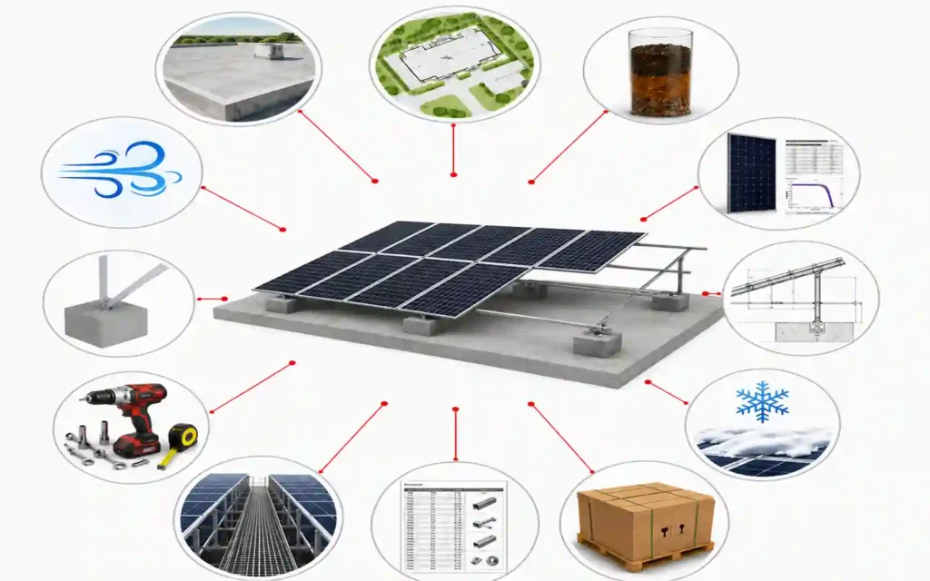
| Project Input | Why It Matters |
|---|---|
| Project country / location | Environment, wind, snow, corrosion, project requirements |
| Installation type | Roof, ground, carport, agrivoltaic, balcony |
| Roof type or site plan | Determines attachment or foundation strategy |
| Roof / structural information | Defines load path and support spacing |
| Soil / geotechnical data | Needed for ground foundations |
| PV module datasheet | Dimensions, frame, weight, mounting zones |
| Module quantity | Structure and component quantities |
| Layout / orientation | Table, rail, clamp and row geometry |
| Tilt / roof slope | Structural geometry and shading |
| Wind requirement | Attachment, bracing and foundation reactions |
| Snow requirement | Member sizing, support spacing, clearance |
| Corrosion environment | Materials, finishes and fasteners |
| Penetration restrictions | Roof mounting strategy |
| Access / maintenance requirements | Layout and service routes |
| Available drawings / photos | Helps confirm project interfaces |
| Target delivery scope | BOM, packaging, engineering and quotation |
For early-stage project organization, the Solar Mounting System Calculator can help structure basic project inputs before detailed engineering review.
Common Questions About Choosing Solar Panel Mounting Options
What are the main solar panel mounting options?
The main categories are roof mounting, ground mounting, solar carports, agrivoltaic structures, balcony mounting, and selected specialized systems. Within each category there are multiple attachment and structural options.
How do I choose between roof mount and ground mount?
Choose based on available roof or land area, structural suitability, energy layout, access, project size, soil, roof condition, installation scope, and lifecycle requirements.
A suitable roof can avoid new land use. Ground mounting offers more geometry and foundation flexibility but requires land and civil work.
What is the best solar mounting system for a flat roof?
There is no universal best system.
Ballasted solar mount, triangle solar mount, concrete foundation solar mount, mechanically attached, and hybrid systems should be compared using roof load capacity, membrane, wind, penetration restrictions, drainage, access, and future roof work.
What is the best solar mounting system for a metal roof?
First identify the metal roof profile.
Standing seam roofs may use compatible seam clamps. Trapezoidal and corrugated roofs commonly use profile brackets, L feet, hanger bolts, rails, mini rails, or other mechanically fastened systems. The triangle solar mount and adjustable solar panel mount may be used at the low-slope metal roofs.
It is necessary to take into account factors such as the latitude, wind speed, snow load, and building height at the specific site.
How do I choose a ground mount foundation?
Begin with soil, groundwater, frost, terrain, structural reactions, project capacity, installation preferences, installation equipment, corrosion, and project restrictions.
Driven piles, ground screws, and concrete foundations are all valid options when matched to appropriate site conditions.
Should I choose aluminum or steel solar mounting?
Do not choose by material name alone.
Compare structural requirements, weight, member geometry, corrosion exposure, coating or anodizing, fastener compatibility, fabrication, installation, transport, and lifecycle needs.
On-site location is very important, if the site is near to the sea, we suggest the aluminum solar racking system for its high corrosion resistance.
How important are wind and snow loads when choosing racking?
They are critical.
Wind and snow can affect rails, beams, posts, bracing, clamps, roof attachments, ballast, foundations, and fasteners. DOE’s design guidance specifically emphasizes engineering racking for environmental loads and critical fastened-joint performance.
The selected configuration should be checked against project-specific loading requirements.
Should I choose a rail-based or rail-less system?
That depends on the roof, module, attachment architecture, adjustment needs, logistics, installation method, and structural requirements.
Rail-less does not automatically mean faster or better; it moves the module-support function into a different interface.
Is the lowest-price mounting system the best option?
Not necessarily.
Compare total installed and lifecycle cost, including engineering, foundations or roof attachments, freight, installation labor, waterproofing, testing, maintenance, roof work, and replacement parts.
What documents should a solar mounting supplier provide?
Depending on project scope, useful documents can include arrangement drawings, structural layouts, BOMs, installation manuals, material information, module compatibility, fastener and torque requirements, grounding details, packing lists, and project-specific engineering information.
Choose the System by Project Constraints, Then Optimize the Details
The most reliable way to choose a solar mounting system is to use the correct decision order.
Start with the constraints that cannot be negotiated:
Site / Roof → Structural Support → Attachment or Foundation → Module → Wind / Snow → Corrosion
Then optimize the remaining choices:
Layout → Installation → Logistics → Maintenance → Lifecycle → Cost
This sequence keeps the mounting system connected to the real project.
It also helps procurement teams compare quotations on equal terms and prevents one attractive product feature from overriding a critical site requirement.
Explore Solar Mounting Systems for roof, ground, carport, agrivoltaic, balcony, and mounting accessory options.
For project-specific guidance, send your project details including the module datasheet, roof or site information, layout, wind and snow requirements, corrosion environment, and available drawings.
References & Technical Sources
- U.S. Department of Energy — Life Cycle of Photovoltaic Systems: Procure a New Photovoltaic System
https://www.energy.gov/cmei/femp/life-cycle-photovoltaic-systems-procure-new-photovoltaic-system - U.S. Department of Energy — Solar Photovoltaic System Design Basics
https://www.energy.gov/cmei/systems/solar-photovoltaic-system-design-basics - U.S. Department of Energy — Life Cycle of Photovoltaic Systems: Install and Commission a Photovoltaic System
https://www.energy.gov/cmei/femp/life-cycle-photovoltaic-systems-install-and-commission-photovoltaic-system - U.S. Department of Energy — Severe Weather Resilience in Solar Photovoltaic System Design
https://www.energy.gov/cmei/femp/severe-weather-resilience-solar-photovoltaic-system-design - U.S. Department of Energy — Managing and Mitigating Solar PV Corrosion
https://www.energy.gov/cmei/femp/managing-and-mitigating-solar-pv-corrosion - Pacific Northwest National Laboratory / Building America Solution Center — Roof Anchor System for Solar Panels
https://basc.pnnl.gov/resource-guides/roof-anchor-system-solar-panels

Sales Manager at Easy Solar Solar Mounting Systems. With over 1o years of experience in the solar industry, I specialize in providing reliable andcost-effective mounting solutions for distributors, installers, and EPC companies. Experienced in intemational sales and commited to building long-term partnerships worldwide.