
Rail-Based vs Railless Solar Mounting Systems: Which Is Better?
Rail-based solar mounting uses continuous rails to support and align PV modules. Railless mounting removes those long rails and relies on localized attachments or module-specific connectors instead. Mini-rail systems sit between the two: they use short rail sections rather than continuous profiles.
For a compatible metal roof, mini-rail or direct-attach mounting may simplify long-profile handling. Conventional rails can provide more flexibility for alignment, attachment locations, and accessory support. Neither solution is automatically cheaper, faster to install, or structurally stronger. The right choice depends on the roof, the PV module, the verified load path, electrical bonding, installation conditions, and total installed scope.
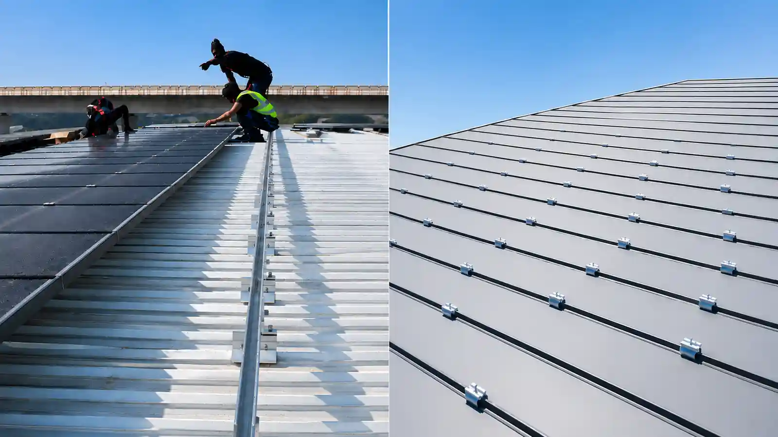
This guide compares all three architectures and uses an Easy Solar 38.4 kWp rooftop design example to explain the differences with actual engineering drawings and bill-of-materials (BOM) data.
Rail-Based vs Mini-Rail vs Railless: Quick Comparison
| Decision factor | Continuous-rail mounting | Mini-rail / short-rail mounting | Direct-attach / railless mounting |
|---|---|---|---|
| Main module-support interface | Long, continuous mounting profiles | Short local rail profiles | Direct brackets, clamps, or module connectors |
| Module alignment | Continuous rail creates a reference line | Alignment depends on the local supports and roof layout | Alignment depends on the attachment and module system |
| Handling and logistics | Long profiles require transport, storage, and roof handling | Short profiles avoid much of the long-profile handling | Often compact components; actual freight depends on the complete kit |
| Installation adjustment | Can offer adjustment through rail and attachment slots | Depends on each mini-rail assembly | Depends on direct mounts and approved adjustment features |
| Module compatibility | Must meet clamp-zone and span requirements | Must match clamps, support locations, and module instructions | Often strongly dependent on specific module frames or connectors |
| Bonding and wiring | Rail may provide part of a verified bonding and cable-support system | Local bonding and cable support must be detailed | System-specific bonding and wire support are essential |
| Typical consideration | Varied attachment positions, alignment flexibility | Compatible profiled metal roofs and shorter material handling | Compatible roofs and approved direct-attachment systems |
Selection rule: First eliminate configurations that cannot meet structural, roof-interface, module, and electrical requirements. Compare labor and cost only among the remaining technically suitable options.
1. How the Three Mounting Architectures Work
Continuous-rail mounting
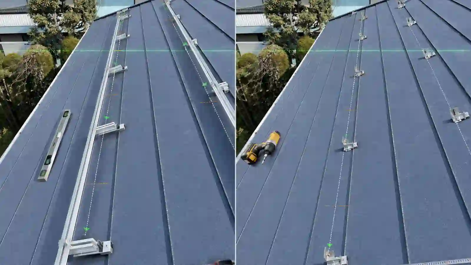
In a conventional roof mounting arrangement, clamps secure PV modules to long aluminum rails, and roof attachments transfer forces from the rails to the building’s supporting structure. Rails also provide a convenient reference for alignment, splices, selected bonding components, and cable accessories.
A typical structural path is:
PV module → module clamp → continuous rail → roof attachment → supporting roof structure.
The actual load path must include every intervening roof connection. For example, a clamp fixed to a standing seam may rely on the capacity of the seam, roof panel, panel clips, and the building’s underlying structure—not just the published clamp capacity.
Mini-rail or short-rail mounting
Mini-rail systems replace continuous profiles with localized lengths of extruded support. On suitable profiled metal roofs, short pieces provide local module clamping and support interfaces. Depending on the product, they may incorporate fasteners and sealing materials in a compact assembly.
The major potential advantage is reduced dependence on long rails, not the elimination of engineering work. Local attachment locations, roof-sheet suitability, approved module clamp zones, watertightness, and bonding still require verification.
Direct-attach or fully railless mounting
Direct-attach systems connect the module to approved roof-mounted devices or system-specific module connectors without continuous rails acting as the principal support line. Some designs clamp standing seams; others use structural fasteners or other approved roof interfaces.
Terminology note: In the market, railless sometimes includes mini-rail products. In this guide, we distinguish continuous rail, mini rail, and direct attach so EPC buyers can compare the physical structures accurately. The 38.4 kWp example below is continuous rail versus mini rail, not a test of every fully railless architecture.
2. The Engineering Differences That Matter
Structural load transfer and roof connections
Removing a long rail changes where forces are collected and transferred. A continuous rail distributes module reactions among attachments according to its span and connection design. A mini-rail or direct-attach system places greater emphasis on the capacities and locations of its localized interfaces.
For either architecture, verify the design loads, module mounting positions, attachment spacing, fastener capacities, and the complete path to the supporting members. On profiled and standing-seam metal roofs, a roof-panel or seam-clamp check alone may be insufficient: roof-panel thickness, seam geometry, underlying clips or fasteners, purlin spacing, and roof movement can also matter.
The 45 m/s wind speed stated on a concept drawing does not by itself prove allowable uplift resistance. Wind-speed definitions, applicable code, exposure, roof zones, geometry, pressure calculations, and connection checks must be established for the actual project. The same principle applies to snow and other design actions. The U.S. Department of Energy’s installation guidance identifies racking and critical fastened joints as important parts of PV structural resilience.
Roof compatibility and waterproofing
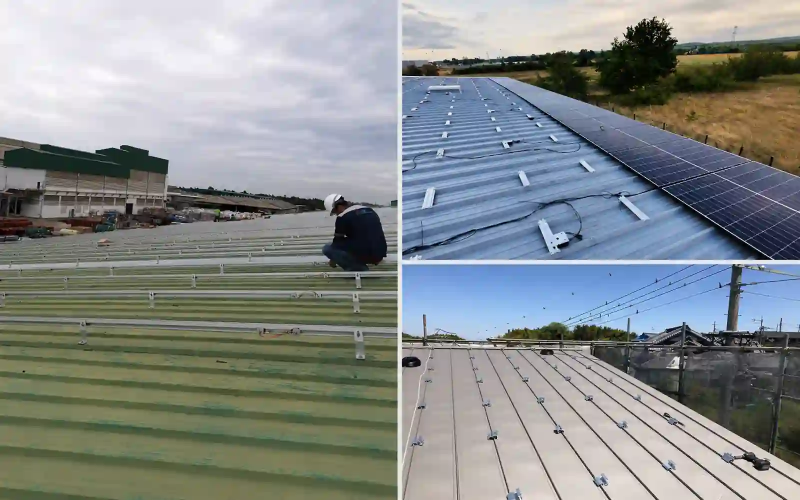
Rail-based and railless systems can both be mechanically attached, while some standing-seam solutions may avoid new penetrations if the seam, clamp, and roof assembly are suitable. Railless does not automatically mean penetration-free.
For a profiled metal roof, request the profile drawing, roof-panel material and thickness, support spacing, fixing details, and approved sealing method. Check whether fasteners engage the intended load-bearing component and whether seals or gaskets suit the roof surface, exposure, and service life.
Module compatibility and installation tolerances
Continuous rails can act as an alignment reference and may provide more flexibility in positioning clamps across attachment locations. Localized systems need a sufficiently accurate roof layout and enough adjustment to accommodate permitted field variation.
In every case, check the exact module installation manual. Module width, length, frame height, allowable clamping zones, installation orientation, and permitted loading configurations can all affect the design. A clamp that fits a nominal 30 mm frame is not automatically an approved mechanical attachment for every 30 mm module.
Electrical bonding, cable routing, and serviceability
Bonding hardware, earthing lugs, module-frame contact points, and cable supports are part of the mounting system—not optional details added after a structural BOM is priced. A rail-based assembly may use the rail as one part of an evaluated bonding path. Short-rail and direct-attach systems need their own documented approach.
Where UL 2703 or another project-required evaluation applies, check the covered mounting components and module combinations, along with the relevant installation instructions. UL Solutions describes the importance of evaluating mounting and bonding arrangements as systems.
Also check wire clearance, connector support, module-level power electronics (MLPE) attachment, inspection access, and module replacement. The U.S. Department of Energy’s cable-management guidance explains why secure, durable cable support matters throughout the PV system’s operating life.
3. Easy Solar Engineering Example: 38.4 kWp Rooftop PV Layout
Easy Solar prepared two preliminary mounting configurations for the same representative eight-module roof array: NF-26102201, using continuous rails, and NF-26102202, using mini rails. The accompanying project note specifies 96 modules × 400 W = 38,400 Wp (38.4 kWp DC), arranged as twelve eight-module groups in the planning calculation.
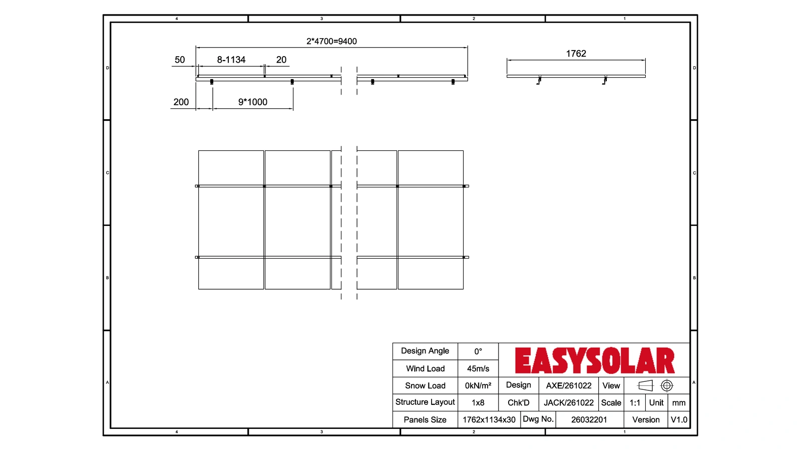
The drawings and BOMs describe one 1 × 8 array unit. They are useful primary engineering records for comparing the material architecture. They are not evidence of a completed installation, measured labor savings, quoted project prices, or final structural approval.
Shared drawing inputs
| Input recorded in both drawings | Value |
|---|---|
| PV module size | 1762 × 1134 × 30 mm |
| Representative array unit | 1 × 8 modules |
| Drawing-listed design angle | 0° |
| Drawing-listed wind-speed input | 45 m/s |
| Drawing-listed snow-load input | 0 kN/m² |
| Planning configuration | 96 modules at 400 W each = 38.4 kWp DC |
The drawings do not establish the relevant roof construction, project location, governing design standard, wind-speed definition, complete connection calculations, or certification coverage. These must be confirmed before construction approval. The 0° value is the drawing’s stated design angle and should not be interpreted without clarification as a measured roof pitch.
Option A: Continuous-rail design (NF-26102201)
Figure 1. Easy Solar preliminary continuous-rail arrangement, drawing NF-26102201. The source drawing shows the 1 × 8 module layout and its support arrangement.
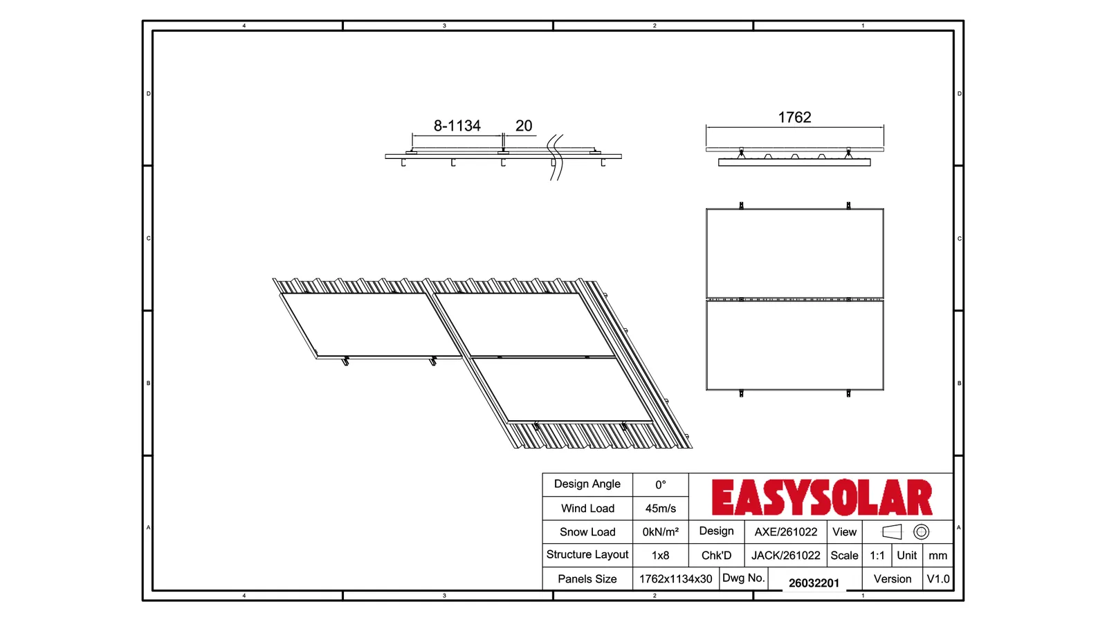
The BOM for the eight-module unit lists four R01 rails, each 4700 mm long (18.8 m of rail pieces in total), joined with two rail connectors. It also specifies 20 L-feet, four end clamps, 14 middle clamps, 14 grounding clips, and two earthing lugs. Materials specified for the main profiles and selected assemblies include AL6005-T5 aluminum and SUS304 stainless steel.
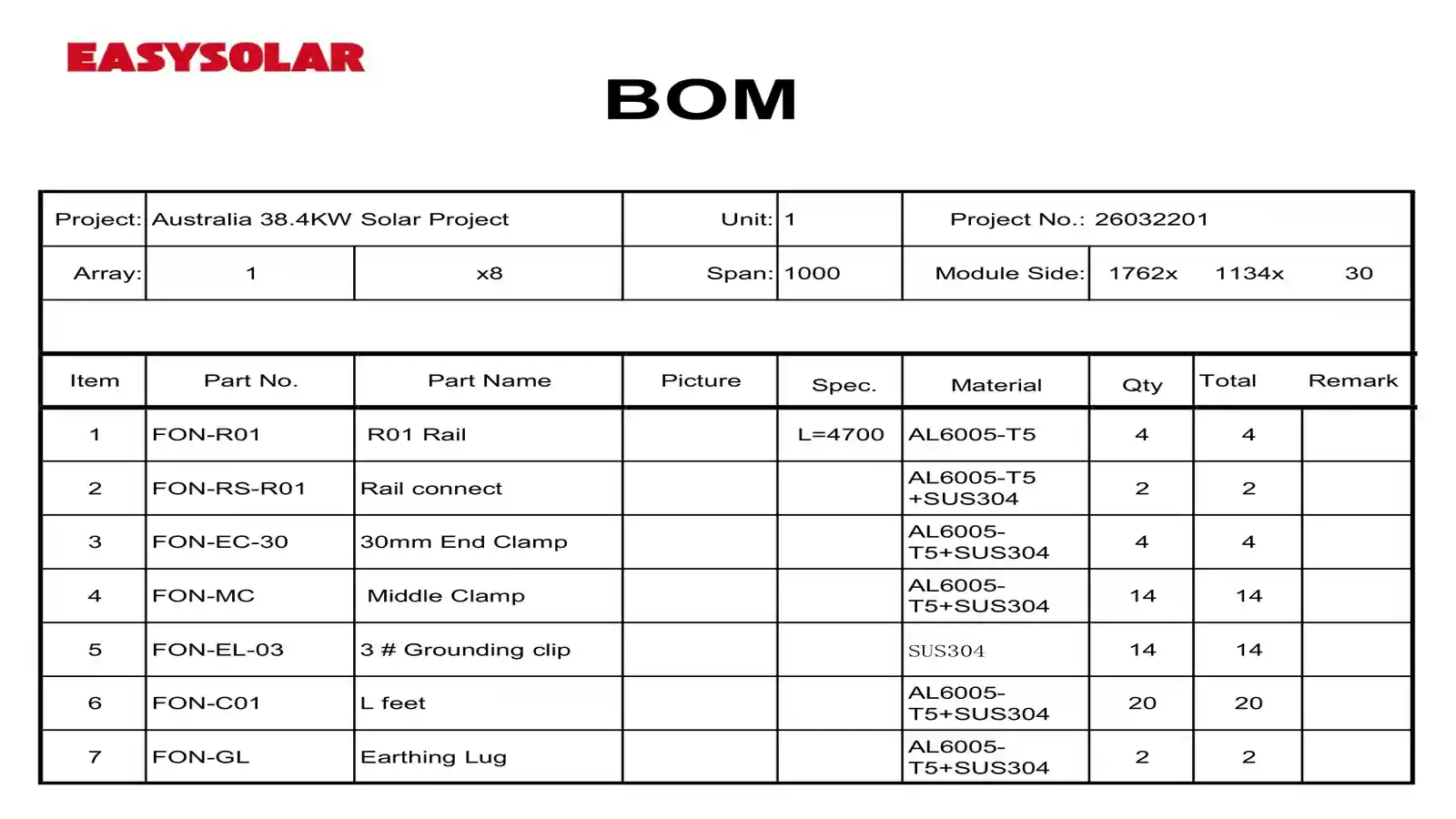
This configuration includes a continuous support and alignment layer, together with separately itemized grounding components. However, the BOM alone does not establish the roof anchorage design or installed cost.
Option B: Railess design (NF-26102202)
Figure 2. Easy Solar preliminary railess arrangement, drawing NF-26102202. Short supports replace the long continuous rail profiles.
The corresponding eight-module BOM lists 18 mini-rail pieces, each 120 mm long and 30 mm high, plus four end clamps and 14 middle clamps. The mini-rail assemblies specify AL6005-T5 aluminum, SUS410 stainless steel, and EPDM. The clamps specify AL6005-T5 and SUS304.
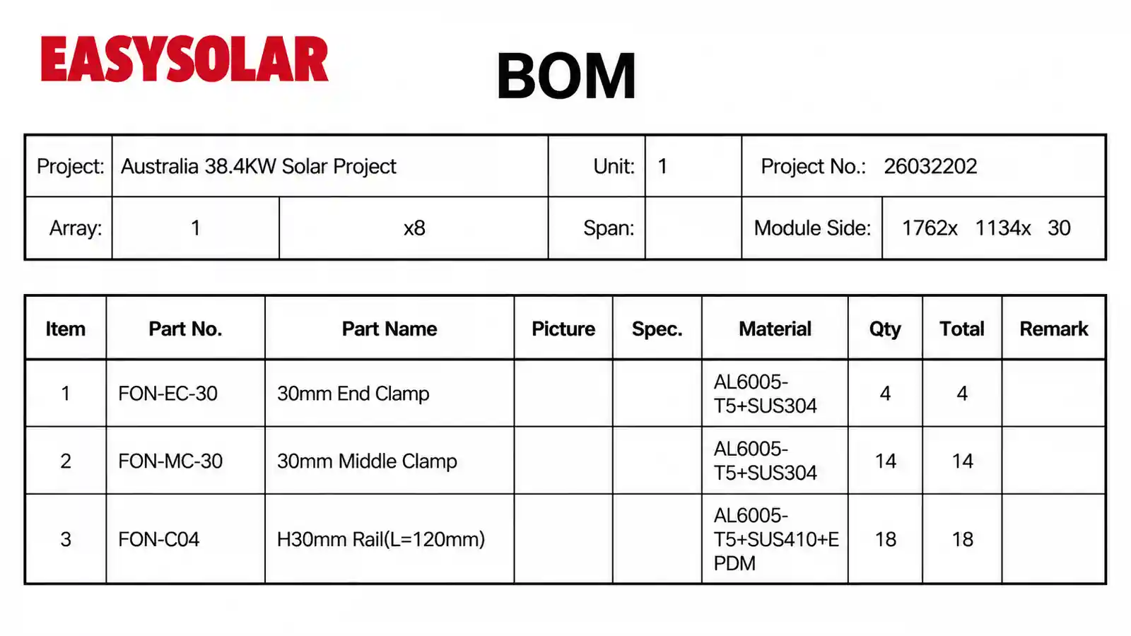
No separate grounding clips or earthing lugs appear in the supplied mini-rail BOM. That does not establish that they are unnecessary. The complete bonding design and the inclusion or exclusion of any additional electrical accessories must be verified independently.
BOM comparison: one eight-module unit
| BOM item | Continuous rail: NF-26102201 | Mini rail: NF-26102202 |
|---|---|---|
| Main supports | 4 × 4700 mm R01 rails | 18 × 120 mm mini rails (H = 30 mm) |
| Total nominal lengths of listed support pieces | 18.8 m | 2.16 m |
| Rail splice/connectors | 2 | No long-rail connectors listed |
| End clamps | 4 | 4 |
| Middle clamps | 14 | 14 |
| L-feet | 20 | Not listed as separate parts |
| Grounding clips | 14 | Not separately listed |
| Earthing lugs | 2 | Not separately listed |
| Main specified profile material | AL6005-T5 | AL6005-T5 |
| Additional specified materials | SUS304 in selected assemblies | SUS410 and EPDM in mini-rail assemblies; SUS304 in clamps |
What the numbers demonstrate: the two proposals have different support architectures and long-profile handling requirements. The listed mini-rail pieces total 2.16 m versus 18.8 m of listed long rail pieces in the conventional BOM.
What they do not demonstrate: an 88.5% reduction in total aluminum mass, system weight, cost, wind demand, or installation time. The profiles have different cross-sections, functions, connections, and accessory requirements. Their summed lengths are not a like-for-like material-performance metric.
What an EPC should conclude from this example
The continuous-rail configuration may be attractive if alignment adjustment, distributed supports, and a familiar installation sequence are project priorities. The mini-rail configuration may be attractive if the roof profile and structural checks support localized attachments and reducing long-profile handling is valuable.
To reach a final choice, the EPC still needs a verified roof connection, the precise module mounting instructions, structural calculations for the project conditions, an approved bonding and cable-management strategy, and comparable installation and delivered-cost assumptions.
The practical lesson is simple: a shorter BOM is not the same as a complete, technically approved, lower-cost installation.
4. Installation and Total Cost: Compare the Whole System
A useful commercial comparison should account for where work is saved and where new work may appear.
| Cost or work package | Questions for the rail option | Questions for the mini-rail/direct-attach option |
|---|---|---|
| Layout and preparation | How are rail lines and roof attachments set out? | How accurately must individual support points be located? |
| Roof work | What are the attachment and waterproofing requirements? | What roof fasteners, sealing details, and interface checks are needed? |
| Support installation | What labor is needed for long-rail staging, cutting, splicing, and alignment? | What labor is needed to position and fasten local mounts? |
| Electrical integration | Which bonding and cable accessories are included? | How is the equivalent scope provided and documented? |
| Logistics | What are the packed rail lengths, weight, and freight terms? | What is the actual packed weight, carton count, and freight cost? |
| Inspection and maintenance | How are clamps, rails, and accessories accessed and replaced? | How are direct or short-rail interfaces accessed and replaced? |
For an objective comparison, request complete project-specific BOMs, assembly drawings, freight assumptions, roof-interface scope, and installer labor assumptions from both options. Use an identical module layout and define all inclusions and exclusions. If on-site work has been measured, show actual installation hours and assumptions rather than marketing estimates.
5. Which Mounting Architecture Should You Choose?
Choose continuous rail as a strong candidate when the roof has varying support locations, adjustment and row alignment are important, installers already use a rail-based workflow, or the project benefits from standardized accessory interfaces. Confirm those potential benefits against the proposed rail and attachment system.
Evaluate mini rails when a profiled metal roof has compatible dimensions and verified attachment points, short-component logistics are valuable, and the module’s prescribed mounting geometry can be met without continuous supports.
Evaluate fully direct-attach/railless systems when the specific roof assembly and PV modules are approved for the selected direct interface, the attachment positions and bonding path are defined, and the installation team can work to the required system-specific tolerances.
Do not select any of them solely by the roof covering’s name. Standing-seam, trapezoidal, corrugated, and other roof constructions can have materially different load paths and fastening requirements. For a broader roof-type discussion, read our solar panel roof mounting systems guide. For the cross-project selection process, see how to choose a solar mounting system.
A five-check decision framework
- Roof and support: Verify roof profile, roof condition, structural members, attachment path, and waterproofing.
- Module compatibility: Confirm the exact module model, manufacturer-approved clamp zones, frame geometry, orientation, and allowable spans.
- Structural design: Establish code-defined wind and snow actions, load combinations, local reactions, and connection capacities.
- Electrical and service integration: Confirm bonding/grounding, cable support, MLPE, inspection access, and future module replacement.
- Installed project value: Compare complete BOMs, labor assumptions, transport, warranties, documentation, and lifecycle service.
If a critical item is unverified, keep the option pending engineering review rather than declaring it suitable or unsuitable on incomplete information.
6. Questions EPC Contractors and Distributors Frequently Ask
Is railless solar mounting always cheaper than a rail-based system?
No. Reducing continuous rail material can change packaging and installation tasks, but total cost also depends on roof attachments, specialized connectors, labor, bonding, waterproofing, shipping, and maintenance. Compare complete installed scopes for the same project.
Does railless mounting require fewer roof penetrations?
Not necessarily. Some compatible standing-seam direct-attachment systems can avoid new penetrations. Other mini-rail and direct-attach systems rely on mechanical fasteners. Penetration count depends on the roof construction, attachment method, and structural design—not on the absence of long rails.
Are rail-based mounting systems stronger than mini-rail systems?
Neither architecture is inherently stronger. Structural performance depends on the full assembly, including module support zones, profile capacities, attachment spacing, fasteners, roof connections, and applicable design loads. Compare documented calculations and test coverage for the specific configuration.
Is mini-rail mounting the same as completely railless mounting?
Not exactly. Mini-rail systems use short localized rail profiles; fully direct-attach arrangements do not use a rail profile as the principal module-support interface. Some suppliers market mini-rail systems under the broader term railless, so request drawings and component specifications rather than relying on product labels.
Does mini-rail mounting improve shipping efficiency?
It can reduce the need to pack and transport long extrusion lengths. However, actual freight savings require the packaged dimensions, total shipment weight, quantities, destination, and freight terms for both complete kits.
Why are grounding clips listed for one Easy Solar option but not the other?
The supplied NF-26102201 BOM separately itemizes 14 grounding clips and two earthing lugs, while NF-26102202 does not separately identify those components. This is a documentation difference, not proof that the mini-rail system can operate without a verified electrical bonding and grounding arrangement. Confirm the final wiring/bonding design before procurement.
What does the 45 m/s value in the engineering drawings mean?
It is the wind-speed input recorded in the preliminary drawings, not an automatically transferable product rating or allowable pressure. The governing code, speed definition, roof zones, project geometry, and structural calculations must be established before the arrangement can be approved for a specific installation.
7. Request a Rail-Based vs Mini-Rail Comparison for Your Project
The best mounting architecture is determined by the actual roof assembly and project constraints—not by the rail label alone.
For an initial review, send Easy Solar your project country, roof profile or section drawing, module model and installation manual, proposed layout, support spacing, and known wind and snow requirements. Add photos, roof structural information, installation constraints, and electrical architecture where available. The engineering team can then clarify suitable options, drawings, BOM scope, and the additional evidence required for a project-specific comparison.
Explore Easy Solar’s engineering support and solar panel mounting rails, or send your rooftop project details for a mounting comparison.
Technical references
- Pacific Northwest National Laboratory / Building America Solution Center — Roof Anchor System for Solar Panels
- U.S. Department of Energy — Install and Commission a Photovoltaic System
- UL Solutions — PV Mounting Systems Certification
- U.S. Department of Energy — Solar Photovoltaic Cable Management
Engineering source materials: Easy Solar drawings NF-26102201 and NF-26102202 and their corresponding BOMs; project configuration note identifying the 96 × 400 W layout. These are preliminary design records supplied for this comparison; they do not establish completion status or project approval.

Sales Manager at Easy Solar Solar Mounting Systems. With over 1o years of experience in the solar industry, I specialize in providing reliable andcost-effective mounting solutions for distributors, installers, and EPC companies. Experienced in intemational sales and commited to building long-term partnerships worldwide.