How Snow Load Affects Solar Racking Design
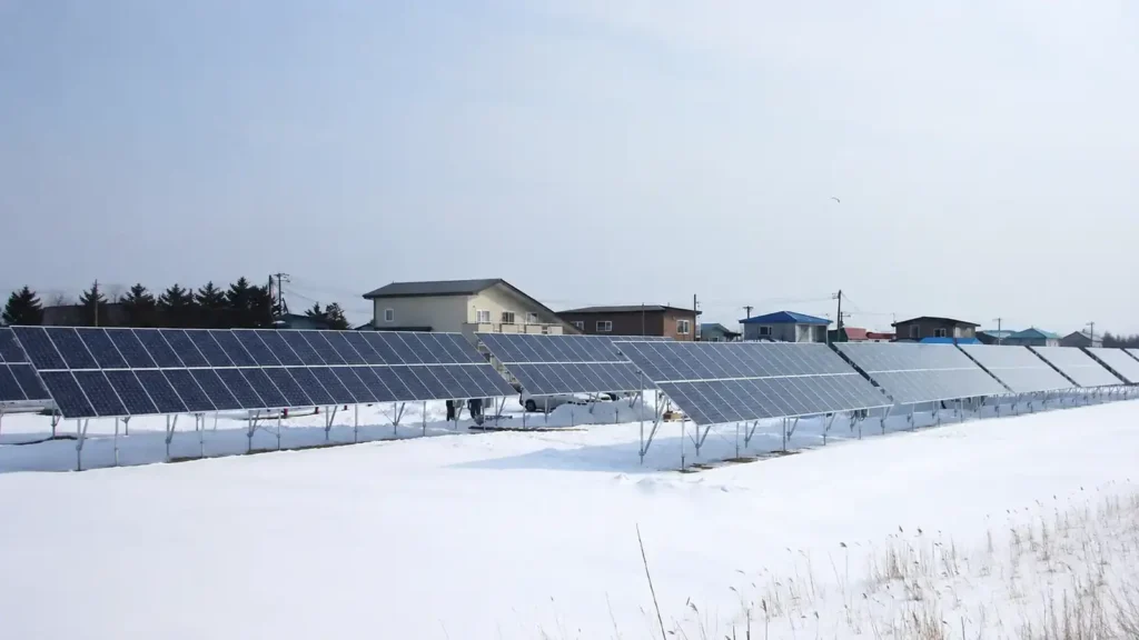
Snow load can govern the design of a solar racking system even when the same structure performs well under wind.
Unlike wind uplift, snow usually adds downward gravity load to the PV modules and supporting structure. But snow is not always distributed uniformly. It can drift, slide, refreeze, accumulate at the lower edge of tilted modules, build up between array rows, or pile around rooftop obstructions. Ice can add weight and redistribute loads again. DOE specifically notes that severe snow and ice can deform modules and overload module frames and supporting structures.
That means a snow-load review is not simply:
Snow Depth × Panel Area = Racking Load
A more useful engineering sequence is:
Site Snow Condition → Code-Based Design Snow Load → Array Geometry → Uniform / Unbalanced / Drift Conditions → Module Support → Rail / Purlin Span → Frame / Attachment → Roof or Foundation → Installation and Inspection
For B2B procurement, the design should then be translated into a project-specific mounting layout, support spacing, structural configuration, bill of materials, and installation requirements.
This guide explains how snow affects rooftop, flat-roof, ground-mounted, carport, and tracking PV structures, and what EPC contractors, installers, developers, and procurement teams should confirm before ordering a solar panel racking system.
For the related wind-design principles, read How Wind Load Affects Solar Panel Mounting Systems.
For broader project selection, see How to Choose a Solar Mounting System for a PV Project.
Snow Load in Solar Racking at a Glance
| Snow Design Question | Why It Matters | Mounting Components Commonly Affected |
|---|---|---|
| What snow-load basis applies at the site? | Establishes the design gravity load for the project | Entire mounting system |
| Can snow accumulate unevenly? | Local loads can exceed a simple uniform-load assumption | Module frame, clamps, rails, roof supports |
| Can snow drift around rows or obstructions? | Drift creates localized surcharge zones | Rails, beams, roof framing, ballast |
| What is the module tilt? | Tilt affects retention, shedding, sliding and wind tradeoffs | Module support, rail span, ground clearance |
| Where can shed snow land? | Snow piles can block drainage, access or the lower module edge | Ground clearance, row spacing, roof layout |
| What is the rail or purlin span? | Gravity loading increases bending and deflection | Rails, purlins, beams |
| How is the module supported? | Mounting points affect frame and glass behavior | Mid/end clamps, direct supports, extra rails |
| What supports the racking? | Roof structure or foundations receive the final reactions | Rafters, purlins, deck, posts, piles, screws |
| Is frost or ice also a concern? | Freeze-thaw and ice can change structural and foundation behavior | Foundations, fasteners, wiring, drainage |
| Has the analyzed configuration reached the BOM? | Engineering and procurement must match | Drawings, support spacing, fasteners, QA |
The main principle is simple:
Snow load is a system requirement, not only a module rating.
1. Snow Load Is Not the Same as Snow Depth
A deep layer of light, dry snow does not create the same load as the same depth of dense, wet snow.
Design standards therefore do not normally ask the racking supplier to estimate structural load directly from a casual observation such as “the site gets one meter of snow.”
Instead, the project should use the snow-load basis required by the applicable code or structural engineer.
For U.S. projects, Department of Energy winter-weather guidance points to ASCE 7 for site-specific snow-load calculations and notes that ground snow load is converted through site-specific factors into the applicable structural design load.
Other markets may use national or regional standards such as Eurocode, NBCC, JIS-based project requirements, or other local design rules.
The project input should therefore identify, where available:
- Applicable design standard
- Ground or roof snow-load parameter
- Project location
- Elevation
- Exposure / site conditions
- Roof or array geometry
- Importance or risk classification where applicable
- Drift or unbalanced-load requirements
- Required load combinations
A supplier should not convert a weather forecast or average snow depth directly into a final structural rating.
2. Uniform Snow Load Is Only the Starting Case
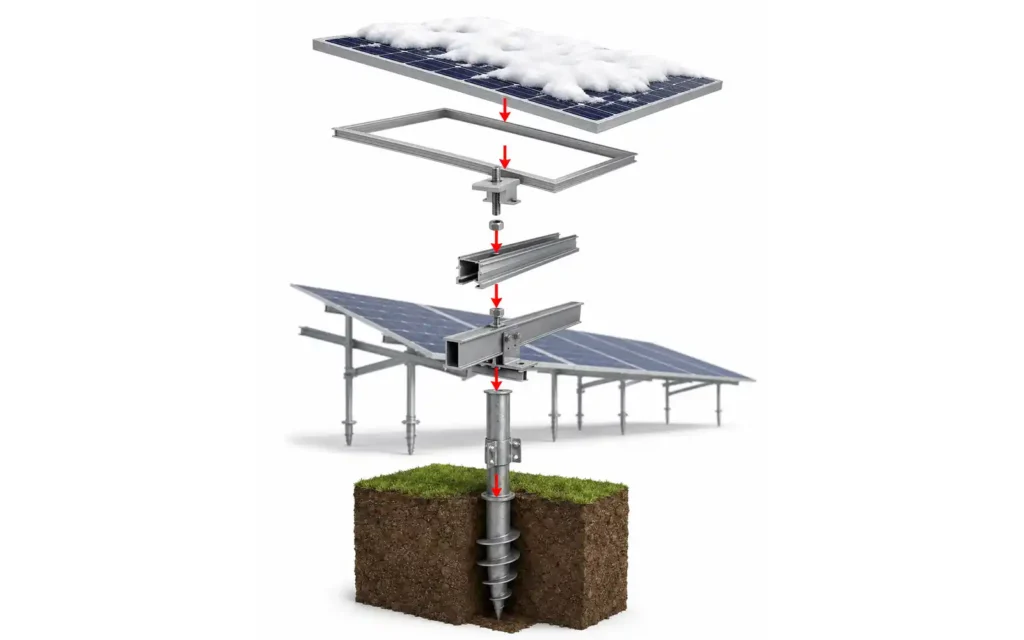
The simplest snow model is a uniform downward load across the module surface.
That is useful for understanding the basic load path:
Snow → Module Glass / Frame → Module Mounting Points → Rails / Purlins → Frame / Roof Attachment → Building or Foundation
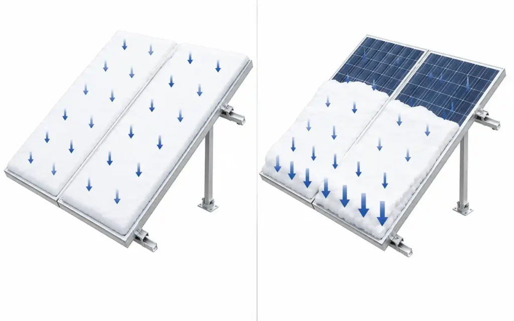
But real snow can be non-uniform.
Possible conditions include:
- More snow at the lower edge of a tilted module
- Partial sliding
- Wind-driven drift
- Snow accumulation behind parapets or rooftop equipment
- Drift between ground-mount rows
- Snow piled beneath the lower edge of the array
- Ice layers that redistribute weight
- Partial melt and refreeze
- Different accumulation on neighboring rows
DOE winter-weather guidance specifically warns against assuming uniform snow loading across PV modules, noting that tilted arrays can become more heavily loaded toward their lower edge.
This matters because a component can pass a uniform-load check while still experiencing a more severe local condition in service.
3. The Module Is Part of the Snow-Load Structure
The PV module is not simply a dead load sitting on the racking.
Its glass, frame, mounting holes, and clamp zones form part of the structural load path.
When reviewing a module for snow conditions, check:
- Published front-side mechanical load rating
- Installation-manual mounting configuration
- Approved clamp zones
- Number of support points
- Portrait or landscape orientation
- Rail or purlin spacing
- Frame thickness and geometry
- Whether the rating applies to the exact mounting arrangement being proposed
DOE advises checking the module’s load rating together with the actual installation configuration because mounting-point quantity and location can affect snow-load performance.
A high module load rating does not automatically mean the complete solar panel racking system has the same capacity.
The module could be strong while:
- The rail span is too long
- The roof attachment is inadequate
- The clamp is outside the approved zone
- The beam deflects excessively
- The post or foundation is undersized
- The roof structure cannot carry the concentrated reactions
The opposite is also true: a robust racking frame cannot compensate for a module mounted outside its approved support condition.
Module rating and racking capacity have to be checked together.
4. Uneven Snow Can Increase Stress at the Lower Module Edge
Tilted PV modules can shed snow, but shedding is not always immediate or complete.
Snow can remain bonded to the glass, accumulate at the frame, or move downward and concentrate near the lower edge.
That can create:
- Higher local module-frame stress
- Greater bending of the lower support rail
- Unequal reactions between upper and lower rails
- Additional demand on lower clamps
- Localized glass deflection
DOE’s Mount Rainier case is a useful real-world example.
At the Sunrise site, heavy snow damaged modules concentrated along the lowest row. Module frames were pulled downward, several modules were damaged or crushed, and the supporting racking was deformed.
The later retrofit added an additional rail, increased the number of module mounting points, and added further backside support. The retrofitted array subsequently survived another severe winter without snow damage.
The lesson is not that every snow project needs an extra rail.
The lesson is:
The actual support configuration matters as much as the nominal module load rating.
5. Snow Load Can Reduce Allowable Rail and Purlin Span
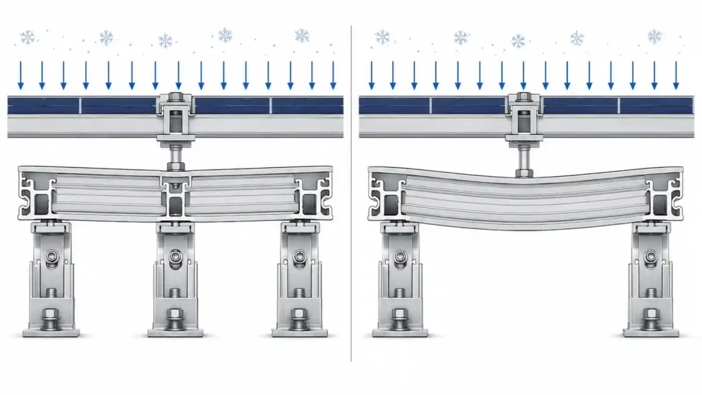
Rails and purlins act as beams between support points.
As snow load increases, bending and deflection demand also increase.
A racking designer may respond by:
- Reducing rail span
- Reducing purlin span
- Selecting a deeper or stiffer profile
- Adding another rail
- Adding intermediate supports
- Reducing cantilever
- Changing module orientation
- Increasing frame or beam capacity
DOE’s winter-hardening guidance similarly recommends more robust racking, additional module attachment/support where appropriate, and avoiding substantial cantilevers in severe winter conditions.
The correct response depends on the structure.
This is why two projects using the same rail profile may have different allowable support spacing.
A supplier should not quote one global rail span without connecting it to:
- Applied load
- Module dimensions
- Rail orientation
- Support spacing
- Cantilever
- Material properties
- Connection details
- Deflection criteria
For component-level options, see Solar Panel Mounting Rails.
6. Serviceability Matters Before a Member Actually Fails
Snow design is not only about preventing collapse.
Excessive deflection can also create problems.
A rail, beam, or module that bends too far under snow may cause:
- Module glass stress
- Frame distortion
- Clamp movement
- Misalignment
- Seal stress
- Contact between parts that were intended to remain separated
- Permanent deformation
- Difficulty removing or replacing modules after the event
The Mount Rainier failure demonstrates why deflection and local support behavior matter even before complete structural collapse: heavy accumulation deformed the racking and module frames in the most highly loaded area.
Structural design therefore checks both strength and serviceability.
For B2B procurement, this matters because two mounting systems can both claim to “carry the snow load” while having different stiffness, span, and deflection behavior.
The engineering package should clarify the analyzed configuration rather than relying only on a maximum load label.
7. Tilt Angle Is a Snow-Shedding Decision and a Wind Decision
Higher tilt can help snow leave the module surface more quickly.
But it does not guarantee that every snowfall will slide off.
Snow shedding depends on factors such as:
- Snow type
- Temperature
- Freeze-thaw conditions
- Module surface
- Frame edge
- Solar heating
- Wind
- Ice bonding
- Tilt
- Whether there is space below the panel for snow to fall
DOE notes that steeper modules can improve snow shedding, but also warns that increasing tilt can increase wind loads.
That creates a structural tradeoff:
Higher Tilt → Potentially Better Snow Shedding → Potentially Higher Wind Demand
The final tilt should therefore coordinate:
- Energy yield
- Snow accumulation
- Wind load
- Row spacing
- Ground / roof clearance
- Ballast or foundation demand
- Structural member size
- Site operation
8. Roof-Mounted PV Can Create New Snow Accumulation Patterns
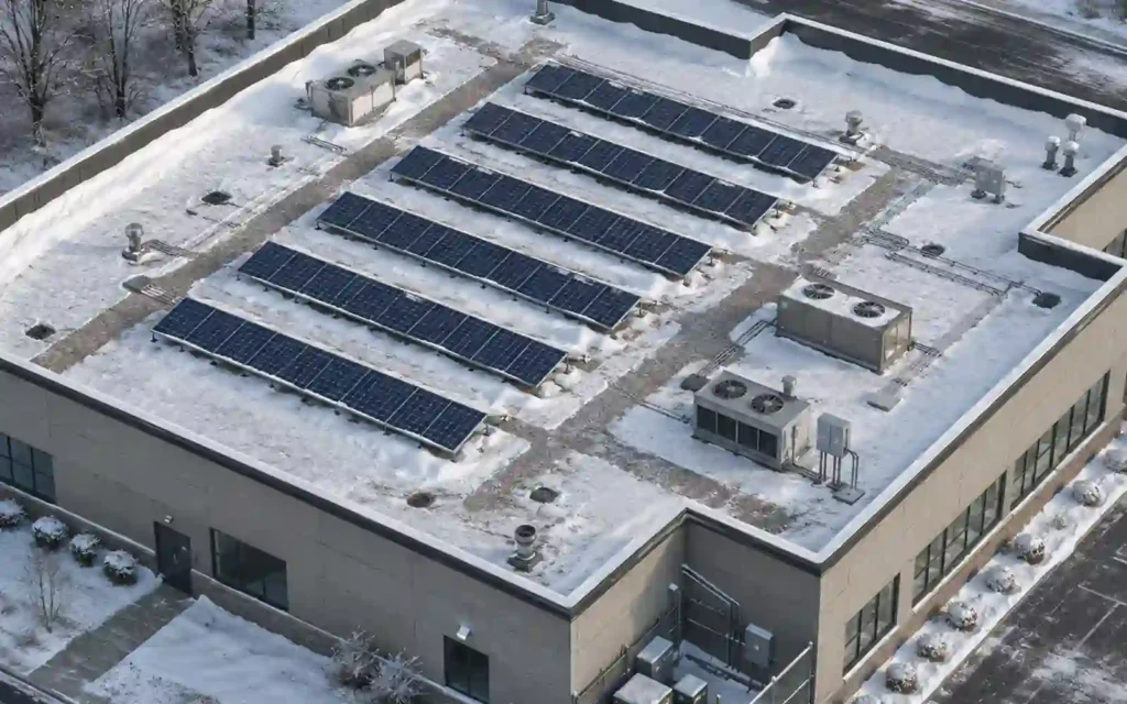
A rooftop PV array changes the roof surface.
Rails, tilted modules, gaps, parapets, and rooftop equipment can alter how snow moves and where it accumulates.
Important areas to review include:
- Roof edges
- Parapets
- Roof steps
- Penthouse walls
- HVAC equipment
- Array perimeter
- Gaps between module groups
- Lower edge of tilted arrays
- Roof drains
- Walkways
The supporting roof also has to receive the concentrated reactions from the mounting system.
PNNL recommends that rooftop mounting-system selection account for both wind and snow loading and that the mounting system be connected appropriately to the supporting roof structure.
A roof may be capable of supporting a distributed snow load but still require review where the racking concentrates reactions into selected rafters, joists, purlins, or deck locations.
For rooftop projects, see Roof Solar Mounting Systems.
9. Flat-Roof Systems Must Combine Snow, Racking Weight and Roof Capacity
Flat-roof PV already adds mounting-system weight to the building.
A ballasted system can add significantly more dead load than a lightweight mechanically attached system.
In a snow climate, the roof structure may therefore need to carry combinations of:
- Existing roof dead load
- PV module weight
- Racking weight
- Ballast
- Snow
- Drift or localized accumulation
- Maintenance loads where applicable
- Other required load combinations
Local structural requirements for solar installations similarly require the supporting roof structure to account for PV, ballast and concentrated racking loads together with applicable snow and wind loads.
The important design question is not simply:
“Can the racking hold the snow?”
It is also:
“Can the roof safely receive the complete PV and snow load through the actual support points?”
This is one reason a ballasted, mechanically attached, or hybrid system should be selected using both roof capacity and environmental loading.
For flat roofs, see Flat Roof Solar Mounting System.
10. Snow Drift Can Create Localized Roof Loads
Wind can move snow after it lands.
When airflow encounters parapets, raised equipment, roof steps, or PV arrays, snow can be transported and deposited in deeper localized drifts.
These drift zones can create structural demands greater than a simple uniform snow layer.
A mounting-system review should therefore coordinate with the building’s snow-drift analysis where required.
Possible design responses can include:
- Moving arrays away from high-drift zones
- Changing row location
- Reducing rail or structural span
- Adding supports
- Strengthening the supporting roof structure
- Adjusting ballast or attachment layout
- Preserving drainage and maintenance access
A generic rooftop racking kit cannot determine this from the module size alone.
11. Ground-Mounted Solar Needs Space for Shed Snow
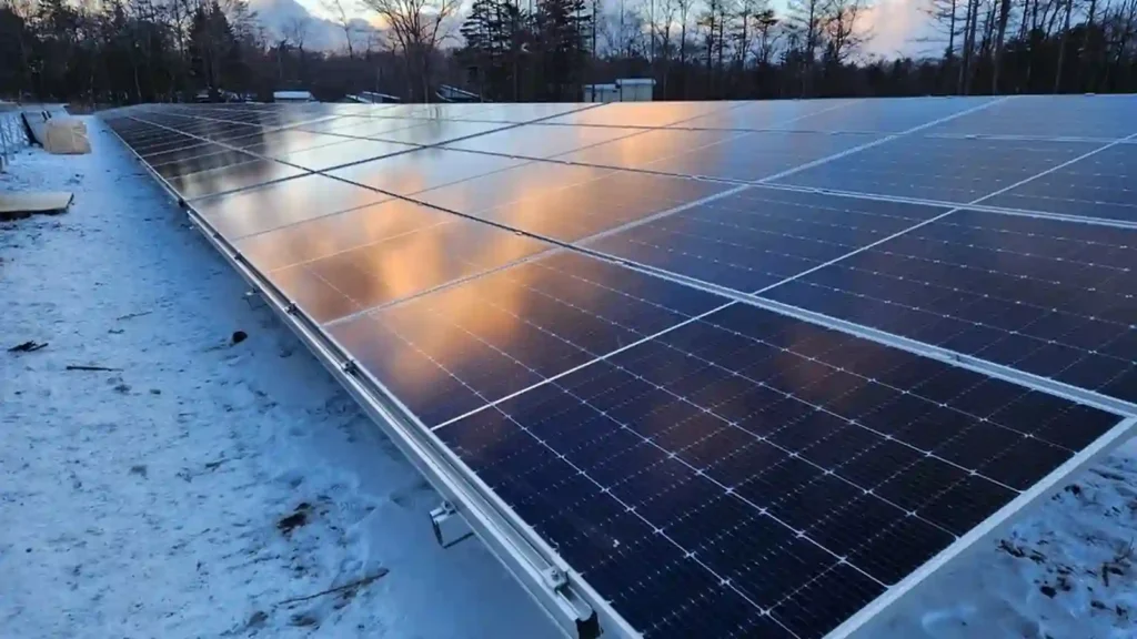
Ground-mounted PV solves the roof-capacity problem but creates another winter issue:
Where does the snow go after it leaves the modules?
Snow can accumulate below the low edge of a fixed-tilt table.
If the lower module edge is too close to the ground, shed snow can build upward until it:
- Blocks further shedding
- Presses against the lower module frame
- Buries cables or equipment
- Reduces maintenance access
- Increases local ice accumulation
- Creates snowplow or site-access conflicts
DOE specifically recommends considering greater clearance below PV modules in heavy-snow regions so that fallen and shed snow has room to accumulate, while also noting that additional structure height can increase wind load and cost.
Ground clearance should therefore consider the expected winter environment, not only vegetation and installation convenience.
For ground projects, see Ground Solar Mounting Systems.
12. Ground-Mount Row Spacing Also Affects Winter Behavior
Row spacing is normally discussed in terms of shading and land use.
In snow climates it also influences:
- Space available for shed snow
- Snow storage between rows
- Access for maintenance
- Snow removal equipment
- Drift behavior
- Vegetation management after snowmelt
- Risk that snow from one row affects the next
DOE notes that additional spacing between modules or PV tables can provide more space for snow shedding and help break up larger masses of accumulated snow.
More spacing can help winter operation, but it also uses more land and changes electrical and civil layouts.
The optimum spacing should therefore balance:
Energy → Land → Access → Snow → Drainage → Construction
This is a useful example of why a solar module mounting structure design should be coordinated across structural, energy, and civil disciplines.
13. Snow Load on Ground Mounts Reaches the Foundations
For a fixed-tilt ground structure, the gravity load path can be:
Snow → Module → Clamp → Rail / Purlin → Beam → Post → Foundation → Soil
Snow generally increases downward compression, but the final design still needs to consider the complete load combinations required for the site.
Foundation effects can include:
- Higher axial compression
- Increased bearing demand
- Frame rotation under uneven load
- Interaction with wind or lateral load cases
- Frost-heave risk
- Freeze-thaw movement
- Settlement in wet or thawing soil
Cold-climate foundation design therefore needs both structural reactions and geotechnical information.
Snow load and frost are different problems, but they occur in the same winter environment and can affect the same structure.
14. Frost Heave Can Move a Ground-Mount Structure Even When the Snow Load Is Acceptable
A pile or ground screw can have enough strength for snow compression and still experience movement from freeze-thaw cycles.
DOE winter-weather guidance recommends accounting for frost depth and site-specific soil conditions in ground-mounted foundation design.
Potential consequences of frost movement include:
- Uneven post elevation
- Table misalignment
- Rail twist
- Module-frame stress
- Changed drainage
- Loosened connections
- Progressive movement between rows
This means a cold-climate ground mount should not stop at a snow-pressure calculation.
The foundation strategy should also address the soil and frost environment.
15. Carports and High-Clearance Structures Carry Snow Through a Larger Frame
A solar carport supports modules above occupied parking space.
Snow load moves through:
Module → Rail / Purlin → Rafter / Beam → Column → Base Plate / Anchor → Foundation
The design can be influenced by:
- Canopy span
- Column spacing
- Module tilt
- Drainage direction
- Snow sliding
- Drift near taller building surfaces
- Uneven loading
- Vehicle and pedestrian areas below
- Foundation conditions
Shed snow also has an operational consequence.
A design should avoid creating uncontrolled snow-fall zones where sliding snow can threaten vehicles, people, equipment, or access routes.
For carport applications, see Solar Carport Mounting System.
16. Trackers Need a Snow Strategy That Does Not Depend on Perfect Operation
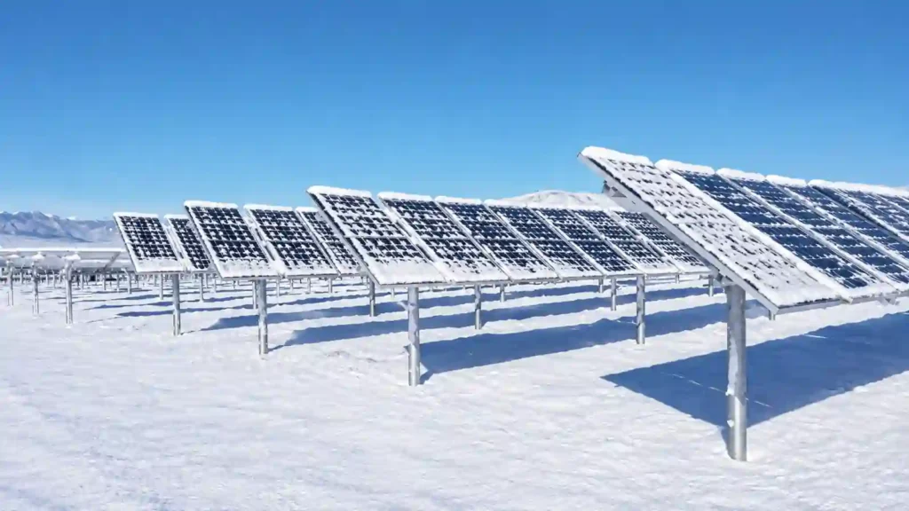
Trackers can move to a steep angle to promote snow shedding.
DOE describes this as a snow stow strategy.
But a design should not assume the tracker will always be able to move exactly as intended during a severe winter event.
Possible issues include:
- Loss of communication
- Loss of power
- Mechanical obstruction
- Frozen components
- Snow already accumulating before stow
- Uneven loading along the row
DOE specifically advises designing for a worst-case condition in which the tracker cannot successfully stow or shed the snow.
The actual tracker mounting points on the module also matter because tracker geometry may support the module differently from a conventional fixed-tilt rail system.
17. Snow and Wind Should Not Be Optimized Separately
Snow and wind often push a mounting design in different directions.
Examples:
- Higher tilt can improve snow shedding but increase wind exposure.
- Higher ground clearance creates more room for shed snow but can increase wind reactions.
- More open row spacing can improve snow storage and access but increases land use.
- Additional module supports can improve snow performance but increase material and installation work.
- Heavier flat-roof ballast may improve wind resistance while increasing the roof dead load that must combine with snow.
DOE winter-weather guidance specifically advises considering combined snow and wind loads rather than designing the two hazards independently.
The project should therefore evaluate the required load combinations rather than selecting one “worst weather number.”
18. Snow Can Create a Zone-Specific Mounting BOM
Like wind, snow does not always produce one identical structural condition across the entire project.
A snow-sensitive design may change selected components or spacing in particular locations.
Possible changes include:
- Additional rails
- Reduced rail span
- Reduced purlin span
- Extra module support points
- Different clamp locations
- Additional beams or braces
- Different roof support spacing
- Higher ground clearance
- Different foundation or post configuration
- Reinforcement in local drift zones
This means:
Snow Analysis → Structural Zones → Mounting Layout → BOM
If the array geometry changes, the snow analysis may need to be reviewed.
If the module changes, the support configuration may need to be reviewed.
If the project moves to a different building or site, an old snow-load BOM should not be reused automatically.
19. Installation Quality Determines Whether the Snow Design Reaches the Field
The snow-load calculation assumes the structure is installed as designed.
Field QA should verify items such as:
- Correct module
- Correct rail or purlin profile
- Correct support spacing
- Correct number of support rails
- Correct clamp zone
- Correct module orientation
- Correct bolts and fasteners
- Required torque
- Correct bracing
- Correct roof attachment
- Correct post / foundation geometry
- No missing supports
- No unauthorized component substitutions
DOE’s installation guidance emphasizes adequate attachment/support points and reliable critical fastened joints for severe winter and storm conditions.
Small installation changes can alter the intended load path.
For example, moving a clamp away from the approved module zone can change module-frame behavior even if the rail itself remains strong.
The structural drawing, BOM, installation manual, and inspection checklist should therefore refer to the same project revision.
20. Winter O&M Should Not Depend on Aggressive Manual Snow Removal
Manual snow removal can introduce new risks.
Shovels, hard tools, stepping on modules, and poorly planned snowplow operations can damage PV equipment.
DOE recommends caution with manual snow removal and advises against stepping on panels or using hard tools that can damage them.
The mounting design should reduce dependence on emergency manual intervention where practical.
Helpful design considerations can include:
- Adequate tilt where appropriate
- Space for shed snow
- Clearly marked array boundaries
- Protected cable routing
- Access routes
- Drainage
- Safe equipment clearance
- Post-storm inspection planning
For sites exposed to severe winter weather, DOE recommends post-event inspection of modules, frames, attachment condition and cable routing.
21. What Snow Information Should You Send a Solar Mounting Supplier?
Do not send only “snow = 1.5 kN/m²” or “snow depth = 80 cm” without the rest of the project context if more information is available.
For a preliminary review, provide:
| Project Input | Why It Matters |
|---|---|
| Project country and exact location | Establishes climate and design jurisdiction |
| Applicable design standard | Defines snow-load methodology |
| Ground / roof snow-load requirement | Main structural input |
| Site elevation | Can affect snow conditions |
| Roof or ground-mount type | Defines load path |
| Roof dimensions / slope | Needed for rooftop geometry |
| Parapets / roof steps / equipment | Can create drift zones |
| Module datasheet | Defines module size, frame and mounting zones |
| Module orientation | Changes support geometry |
| Tilt angle | Influences accumulation and shedding |
| Rail / purlin direction | Affects structural span |
| Support spacing | Influences bending and deflection |
| Ground clearance | Important for shed snow |
| Row spacing | Influences winter storage and access |
| Foundation / soil data | Needed for ground structures |
| Wind-load requirement | Needed for combined design decisions |
| Project drawings / photos | Helps verify actual geometry |
If a structural engineer has already determined design snow pressures, drift zones, or support reactions, provide that information directly.
22. What Should the Mounting Supplier Return?
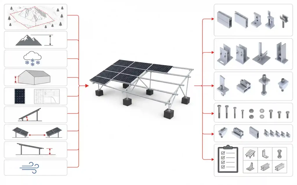
A useful engineering handoff can include:
- Mounting layout
- Rail / purlin profile
- Support spacing
- Module support points
- Clamp locations
- Beam / post configuration
- Bracing requirements
- Roof attachment layout
- Foundation requirements
- Ground-clearance requirement
- Bill of materials
- Fastener specification
- Installation torque
- Design assumptions
- Material / finish information
- Installation instructions
- Required inspection items
- Limits or exclusions
For high-snow projects, the supplier should also clearly identify whether the proposed configuration depends on a specific module mounting arrangement or additional support points.
Procurement should verify that the production BOM matches the latest approved engineering revision.
Common Mistakes in Solar Racking Snow Design
Using Snow Depth as the Structural Load
Depth alone does not define structural pressure.
Assuming the Load Is Uniform
Tilted modules, drift, sliding and ice can create uneven load. DOE explicitly warns against assuming uniform loading on inclined PV.
Looking Only at the Module’s Pa Rating
The complete load path includes clamps, rails, frames, roof supports and foundations.
Using the Same Rail Span in Every Snow Zone
Allowable span depends on load, section, support condition and deflection criteria.
Assuming a Steep Tilt Will Always Keep Panels Clear
Snow can adhere, refreeze or accumulate at the lower edge.
Ignoring Where Shed Snow Lands
The space below and between arrays is part of winter design.
Ignoring Roof Drift Zones
PV can interact with parapets, roof steps and equipment.
Ignoring Frost on Ground-Mounted Systems
Snow pressure and frost heave are different checks.
Reusing a Wind-Optimized Design Without Snow Verification
The structural member that works for uplift may not be adequate for gravity bending or deflection.
Reusing an Old BOM After the Module or Layout Changes
Module dimensions and support locations can change the structural response.
Common Questions About Snow Load and Solar Racking
What is snow load on a solar racking system?
Snow load is the gravity load created by accumulated snow and ice on or around the PV array. It transfers from the module through mounting points, rails or purlins, frames, attachments, and finally into the roof or foundations.
How much snow can a solar panel hold?
There is no universal answer.
Module mechanical-load capacity depends on the specific module and the approved mounting configuration. DOE recommends checking the manufacturer’s installation documentation and the load rating associated with the actual support arrangement.
Is a module rated for 5400 Pa automatically safe in a 5400 Pa snow project?
Not automatically.
The module rating, test condition, mounting arrangement, racking capacity, roof or foundation capacity, and project design load all need to be compatible.
Does a steeper solar panel angle reduce snow load?
A steeper tilt can improve shedding and may reduce retained snow in some conditions, but the final effect depends on climate, ice bonding, array geometry and the applicable design method. Steeper tilt can also increase wind demand.
Can snow load change solar rail spacing?
Yes.
Higher gravity load can require shorter rail spans, more support points, a stiffer rail section, or another structural change depending on the mounting system.
Why does snow accumulate at the bottom of solar panels?
Gravity can move snow downslope while the module frame or cold conditions prevent complete shedding, producing non-uniform accumulation near the lower edge. DOE specifically identifies this lower-edge loading mechanism.
Does a ground-mounted solar array need more clearance in snow regions?
Often, additional clearance should be evaluated so shed and accumulated snow does not reach the lower module edge. The final height should balance snow storage, wind load, cost and site use.
Does row spacing affect snow performance?
Yes.
Row spacing influences where shed snow accumulates, maintenance access and drift behavior. It should be considered together with energy yield and land use.
Are flat-roof solar systems harder to design for snow?
They can require careful coordination because roof capacity must carry the PV system, ballast where used, and snow or drift loads through actual support points.
Do trackers need a snow-stow mode?
Snow stow can be valuable in heavy-snow climates, but the project should still define a structural worst-case condition in case the tracker cannot move as intended during an event.
What information is needed for a snow-load mounting quotation?
Provide project location, applicable design standard, snow-load requirement, module datasheet, tilt, layout, roof or site geometry, support spacing, ground clearance, wind requirement, and available structural drawings.
Design the Snow Load Through the Whole System
A reliable snow-resistant solar structure is not created by choosing a stronger rail or a higher-rated module in isolation.
The design must connect the complete winter load path:
Snow / Ice → Module → Mounting Point → Rail / Purlin → Frame → Roof Attachment / Foundation → Supporting Structure
It must also account for where snow accumulates, where it drifts, where it sheds, and how the installed system will be inspected after severe winter events.
For procurement, the most important practice is to keep the snow-load basis, structural layout, module mounting configuration, BOM, and installation documentation on the same project revision.
Explore Solar Mounting Systems for project-specific roof, ground, carport, agrivoltaic, and mounting-component options.
For rooftop projects, see Roof Solar Mounting Systems.
For ground-mounted projects, see Ground Solar Mounting Systems.
For a project-specific review, send your snow load requirements together with the module datasheet, mounting type, tilt, layout, roof or site information, wind requirement, and available structural drawings.
References & Technical Sources
- U.S. Department of Energy — Solar Photovoltaic Hardening for Resilience: Winter Weather
https://www.energy.gov/cmei/femp/solar-photovoltaic-hardening-resilience-winter-weather - U.S. Department of Energy — Successful Deployment of a Solar Power System at Mount Rainier National Park
https://www.energy.gov/cmei/femp/successful-deployment-solar-power-system-mount-rainier-national-park - U.S. Department of Energy — Life Cycle of Photovoltaic Systems: Install and Commission a Photovoltaic System
https://www.energy.gov/cmei/femp/life-cycle-photovoltaic-systems-install-and-commission-photovoltaic-system - U.S. Department of Energy — Severe Weather Resilience in Solar Photovoltaic System Design
https://www.energy.gov/cmei/femp/severe-weather-resilience-solar-photovoltaic-system-design - Pacific Northwest National Laboratory / Building America Solution Center — Roof Anchor System for Solar Panels
https://basc.pnnl.gov/resource-guides/roof-anchor-system-solar-panels - City of Portland — Structural Design Requirements for Solar Installations
https://www.portland.gov/ppd/solar-development/structural-engineering/structural-design-requirements-solar-installations

Sales Manager at Easy Solar Solar Mounting Systems. With over 1o years of experience in the solar industry, I specialize in providing reliable andcost-effective mounting solutions for distributors, installers, and EPC companies. Experienced in intemational sales and commited to building long-term partnerships worldwide.