
How Wind Load Affects Solar Panel Mounting Systems
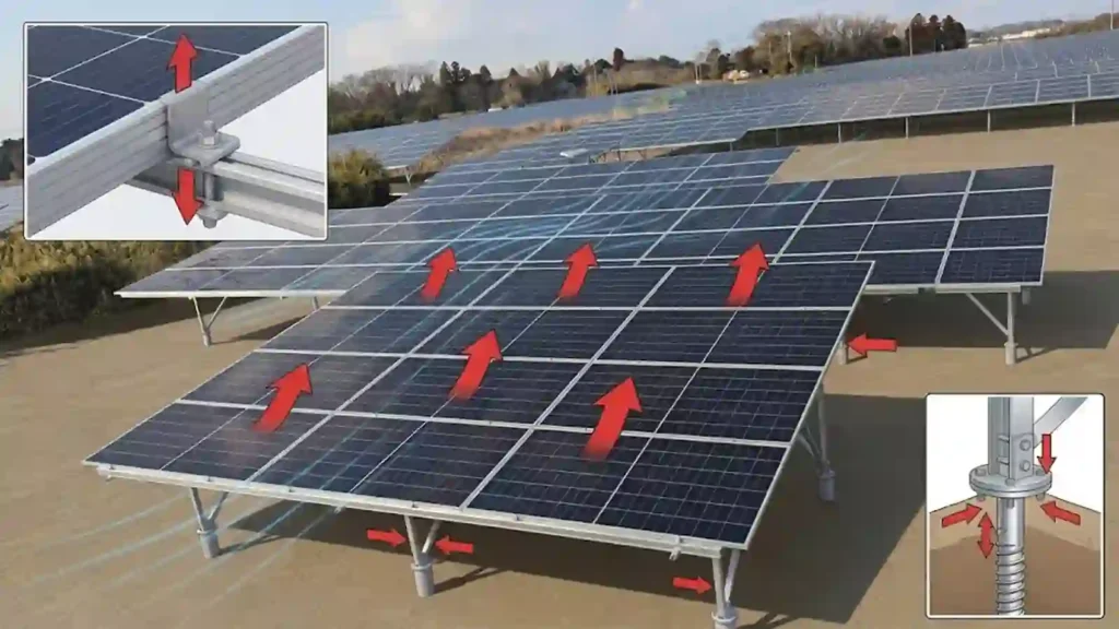
Wind load can change almost every structural decision in a solar mounting system.
It can change the number and spacing of roof attachments, the size and span of rails, the demand on module clamps and fasteners, the amount and distribution of ballast, the need for bracing, the reactions at ground foundations, and the way a tracker is controlled during severe weather.
This is why a statement such as “the racking is rated for 60 m/s wind” is not enough to define whether a mounting system is suitable for a project.
Wind speed is only one input.
The actual structural demand also depends on building or array height, terrain and exposure, roof geometry, array location, panel tilt, module dimensions, gaps below the modules, parapets, row geometry, attachment configuration, and the applicable design standard. DOE similarly treats wind resistance as a whole-system design requirement rather than a single product characteristic.
A better way to understand solar mounting wind design is as a chain:
Site Wind Conditions → Exposure and Height → Array Aerodynamics → Local Wind Zones → Component Reactions → Attachments / Foundations → Installation and Inspection
This guide explains that chain for rooftop, flat-roof, ground-mounted, carport, and tracking PV systems without replacing the project-specific calculations required by the applicable code or structural engineer.
For broader mounting-system selection, see How to Choose a Solar Mounting System for a PV Project.
For the physical connection chain from module to structure, see How Are Solar Panels Mounted?
Wind Load in Solar Mounting at a Glance
| Wind Design Question | Why It Matters to the Mounting System | Components Commonly Affected |
|---|---|---|
| What is the project design wind condition? | Establishes the basic wind environment for the site | Entire structural system |
| How exposed is the site? | Open terrain, coastline, surrounding buildings, and topography affect the wind reaching the array | Rails, frames, attachments, foundations |
| How high is the array? | Wind conditions change with height and building geometry | Roof attachments, ballast, carport/agrivoltaic columns |
| Where is the module in the array? | Edge and corner positions can experience different aerodynamic demand from interior modules | Clamps, rails, roof attachments, ballast |
| What is the module tilt? | Changes the aerodynamic surface presented to the wind | Rails, frame, ballast, posts, foundations |
| How is the module connected? | The load must pass through clamps, bolts, rails, brackets, or direct mounts | Critical fastened joints |
| What supports the racking? | Roof structure, ballast, piles, screws, or concrete must receive the final reactions | Roof structure / foundation |
| Can the structure move or twist? | Excessive flexing can increase stress on modules and fasteners | Bracing, beams, posts, tracker structure |
| How is the design documented? | Procurement and installation must match the analyzed configuration | Drawings, BOM, torque, inspection records |
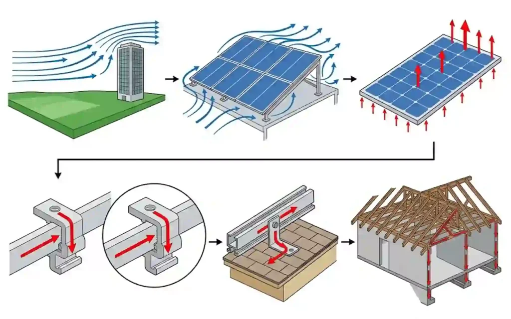
Wind design is therefore not a single product rating. It is a project-specific load path.
1. Wind Creates More Than One Type of Force
The most visible concern is often uplift, where negative pressure or suction tends to pull modules and racking away from the supporting structure.
But a mounting system can also experience:
- Downward pressure
- Lateral force
- Sliding demand
- Overturning
- Torsion
- Frame deflection
- Vibration
- Repeated cyclic loading
- Unequal reactions between different supports
The governing effect depends on the mounting geometry and site conditions.
On a rooftop, uplift can govern the attachment of rails or brackets to the building.
On a ballasted flat roof, wind can drive uplift, sliding, and overturning resistance.
On a fixed-tilt ground mount, wind can create uplift at some posts or foundations while simultaneously producing compression and lateral reactions elsewhere.
On a carport, the wind load has to pass through the canopy beams and columns into the foundations.
On a tracker, wind also interacts with a structure that can rotate and may use a designed stow position.
DOE’s severe-weather guidance emphasizes that PV racking must resist turbulent wind from multiple directions and that significant frame flexing or torsional movement can transfer damaging loads into modules and fasteners.
The complete system therefore needs to resist both the magnitude and the direction of the reactions created by the wind.
2. Design Wind Speed Is an Input, Not a Complete Racking Rating
Buyers often ask a supplier:
“Can this system withstand 45 m/s, 50 m/s, or 60 m/s wind?”
The question is useful, but incomplete.
The same nominal wind speed can create different mounting-system demands on:
- A low warehouse surrounded by other buildings
- A tall exposed industrial roof
- An open coastal ground-mount site
- A high-clearance agricultural structure
- A parking canopy
- A low-tilt ballasted array behind a parapet
The mounting geometry also changes the result.
A module installed nearly flush with a pitched roof does not interact with wind in exactly the same way as a tilted flat-roof array or elevated ground structure.
For that reason, a responsible wind review needs more than a wind-speed number.
The project should identify the applicable standard and the site-specific design inputs required by that standard.
For U.S. projects, current DOE guidance points designers to ASCE/SEI 7-22 and related PV engineering guidance when addressing severe wind.
For projects in other markets, the relevant national or regional wind-loading standard should be used.
A supplier’s catalog wind value can be a useful screening reference, but it should not replace the project calculation.
3. Terrain and Exposure Change the Wind Reaching the Array
Wind does not approach every site under the same conditions.
Surrounding terrain can change turbulence and wind speed near the PV structure.
Important site conditions can include:
- Dense urban development
- Suburban buildings and trees
- Open agricultural land
- Large unobstructed fields
- Coastal or waterfront exposure
- Ridges and escarpments
- Local hills or topographic acceleration
- Nearby tall buildings or industrial structures
This matters because many solar projects are relatively open structures.
A ground mount in an open field can be more exposed than a low rooftop protected by surrounding buildings.
A high-clearance agrivoltaic structure can present more elevation and open area to the wind than a conventional low ground mount.
A carport near an open parking area can also have a different wind environment from a roof-mounted array.
DOE’s current installation guidance explicitly includes topography and site conditions when discussing ground-mounted PV in severe-weather environments.
The terrain/exposure assumption used in engineering should match the actual site rather than being selected from a generic company standard.
4. Building Height and Array Height Matter
For rooftop systems, building height is a major project input.
A 5 m-high warehouse and a 25 m-high commercial building should not automatically use the same attachment spacing or ballast layout simply because the module, tilt, and racking product are identical.
Roof geometry also matters.
Important inputs include:
- Mean roof height
- Roof slope
- Building width and length
- Parapet height
- Roof edges
- Roof corners
- Penthouse or rooftop equipment
- Array setback
- Module elevation above the roof
For ground-mounted, carport, and agrivoltaic structures, array clearance and column height influence the geometry exposed to wind.
Greater clearance can also increase the moment transferred into posts, columns, braces, and foundations.
This does not mean that taller structures are automatically unsuitable.
It means height must be included in the structural model and the product configuration.
5. Rooftop Arrays Do Not Have Uniform Wind Demand
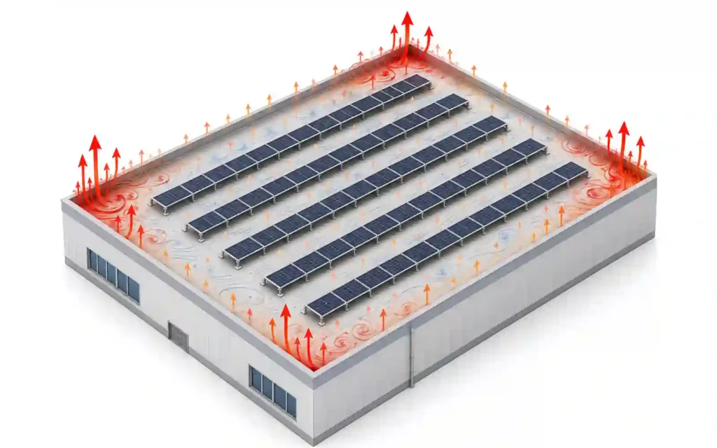
One of the most important concepts in rooftop PV wind design is that modules in different roof locations can experience different aerodynamic conditions.
Roof edges and corners can be particularly demanding because wind separates and forms strong local pressure regions around the building perimeter. Wind-tunnel research on rooftop PV has found corner-vortex effects to be especially important to peak uplift behavior.
That means an array should not automatically use one attachment or ballast pattern across the entire roof.
Depending on the engineered system, perimeter or corner areas may require:
- Closer attachment spacing
- Additional roof attachments
- Different ballast distribution
- Different module setbacks
- Different rail spans
- Additional structural measures
- Avoidance of selected high-demand areas
PNNL likewise notes that wind demand can vary with roof location and that rooftop PV anchoring must be designed around the actual roof and structural conditions.
This creates an important procurement concept:
The mounting BOM can be zone-dependent.
Two modules using the same rail and clamp may require different support conditions because one is located in an interior roof area and another is near an edge or corner.
6. Wind Load Travels Through a Complete Structural Load Path
Wind does not act on “the racking” as one undivided product.
The force starts at the module and moves through multiple interfaces.
A typical rail-based rooftop load path is:
PV Module → Module Clamp → Rail → Roof Bracket / L Foot / Seam Clamp → Roof Structure
A ground-mount path can be:
PV Module → Clamp → Rail / Purlin → Beam → Brace / Post → Foundation → Soil
A carport path can be:
PV Module → Purlin → Main Beam → Column → Base Plate / Anchor → Concrete Foundation → Soil
Every interface has to be adequate.
A strong rail cannot compensate for a weak roof attachment.
A high-capacity roof anchor cannot compensate for a module clamp that is outside the approved mounting zone.
A large ground pile cannot compensate for inadequate bracing or a weak beam-to-post connection.
DOE specifically treats fasteners, brackets, module mounts, foundation connections and roof attachments as critical structural joints in this load path.
This is why wind design must be checked as a connected system.
7. Module Clamps and Fastened Joints Are Critical Under Wind
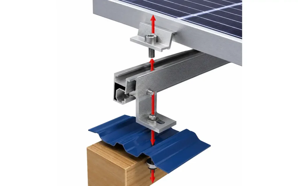
PV mounting systems contain many bolted and clamped joints.
Examples include:
- Module mid clamps
- End clamps
- Rail-to-bracket bolts
- Rail clamps
- Rail splice fasteners
- L-feet
- Roof attachment fasteners
- Beam-to-post bolts
- Brace connections
- Base-plate anchors
- Foundation connection bolts
Wind can subject these joints to repeated movement and vibration in addition to the peak structural demand.
Poorly installed or inadequately designed joints can loosen, slip, rotate, or fail.
DOE identifies several observed failure modes in critical PV fastened joints, including insufficient strength, poor installation, vibration-induced loosening, joint relaxation and module clamp failure.
For module clamps, verify:
- Module frame compatibility
- Approved mounting zone
- Clamp engagement
- Bolt and nut interface
- Installation torque
- Surface condition
- Required number of support points
- Structural rating of the complete connection
For structural bolts, verify the specified bolt, washer, nut, locking method, and installation procedure.
One generic torque value should not be applied to unrelated joints.
The approved mounting-system documentation should define the required installation conditions.
8. Wind Can Change Rail Span and Attachment Spacing
A rail does more than keep modules straight.
It spans between structural support points and transfers module reactions into the attachments.
When wind demand increases, the design may respond by changing:
- Attachment spacing
- Rail span
- Rail section
- Rail orientation
- Number of rails
- Module support points
- Clamp spacing
- Bracket configuration
- Connection hardware
The final change depends on the system.
It is therefore misleading to compare two rails only by section size or aluminum weight.
A smaller rail at shorter support spacing can behave differently from a larger rail at longer spacing.
The relevant comparison is the complete engineered configuration.
9. Pitched Roof Wind Design Is Mainly an Attachment-and-Load-Path Problem
On pitched roofs, the PV array is often mounted relatively close to the roof surface.
The wind design still needs to connect module reactions into the roof structure.
Important inputs include:
- Roof slope
- Building height
- Array position
- Roof edge and ridge location
- Rafter or purlin spacing
- Attachment type
- Attachment embedment or structural connection
- Rail span
- Module orientation
- Module clamp zone
The visible roof covering is not always the final structural support.
For example, a roof hook or L foot may transfer load into a rafter or purlin below the roof covering.
If the fastener misses the intended structural member, a strong rail does not solve the problem.
PNNL specifically recommends that rooftop PV attachments connect appropriately into structural members and that installers verify the actual structural connection rather than relying on roof sheathing alone.
The wind design therefore needs to coordinate the calculated attachment reactions with the actual roof structure and the waterproofing method.
10. Metal Roof Systems Add Profile and Attachment Compatibility
Metal roofs can use several wind-load paths.
Standing Seam
A compatible seam clamp can create a non-penetrating attachment.
The wind load path may be:
Module → Clamp → Rail / Direct Mount → Seam Clamp → Standing Seam Roof System
The seam geometry, clamp interface, roof panel system, and project loads all matter.
Trapezoidal or Corrugated Roof
These roofs commonly use profile brackets, L feet, hanger bolts, mini rails, or other mechanically fastened attachments.
Wind design needs to confirm:
- Roof rib or corrugation geometry
- Purlin or substructure location
- Fastener type
- Fastener quantity
- Sealing detail
- Bracket spacing
- Module support spacing
- Corrosion compatibility
The phrase “metal roof solar mounting” is therefore not enough to define wind performance.
11. Flat-Roof Wind Design Changes Ballast and Attachment Strategy
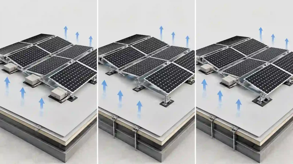
Flat-roof arrays often have low module tilt, but the wind still creates uplift and sliding demand.
A ballasted system uses system weight, ballast distribution, friction, geometry, and aerodynamic behavior as part of its resistance strategy.
A mechanically attached system transfers reactions into the building structure.
A hybrid system combines ballast with selected mechanical attachments.
Wind can change:
- Ballast quantity
- Ballast position
- Perimeter and corner treatment
- Module tilt
- Row spacing
- Wind-deflector configuration
- Mechanical attachment locations
- Roof load distribution
Building height, parapets, array location, and roof geometry also affect the decision.
DOE recommends strategic mechanical attachments rather than relying solely on fully ballasted rooftop systems where severe wind risk makes that approach vulnerable.
This does not mean ballasted systems are inherently unsuitable.
It means the project engineer needs to determine whether the ballast demand, roof capacity, friction assumptions, geometry, and attachment strategy are acceptable.
This broad article does not calculate ballast. That should be done using the specific racking system, roof, wind zones, friction assumptions, and structural design.
12. Ground-Mount Wind Load Reaches the Foundation
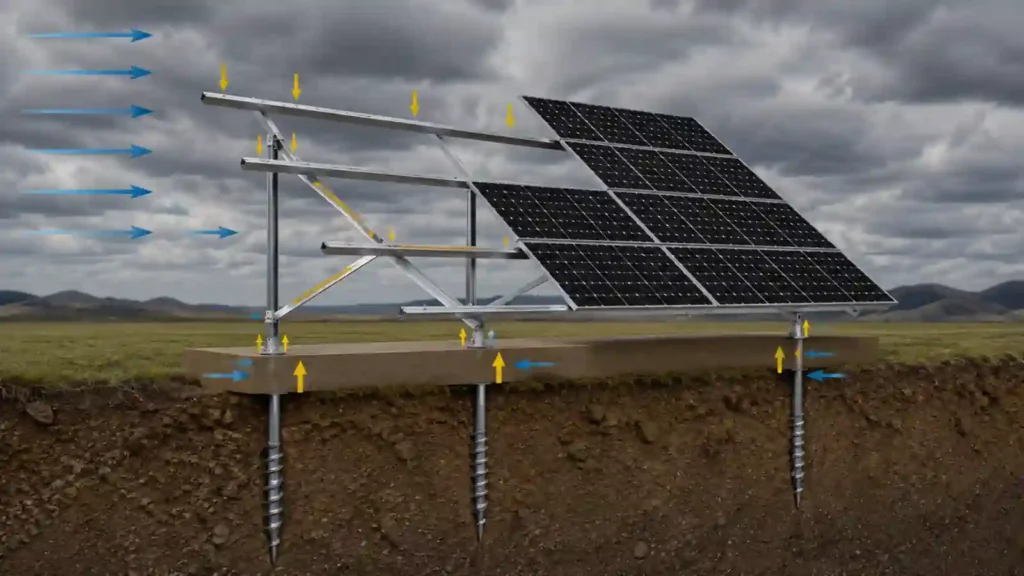
For fixed-tilt ground-mounted solar, the wind load moves through the full free-standing structure.
The structural system may include:
- Module clamps
- Rails
- Beams
- Braces
- Posts
- Base
- Driven piles
- Ground screws
- Concrete foundations
Wind can create combinations of:
- Uplift
- Compression
- Lateral load
- Overturning
- Frame torsion
- Foundation moment
Open terrain, table tilt, table height, module arrangement, row position, and foundation conditions all influence the design.
Lateral bracing becomes particularly important where the frame contains taller vertical members or is susceptible to sideways movement. DOE specifically recommends designing racking to resist lateral movement from multiple wind approach directions.
A separate ground-mount wind guide should go deeper into exposure, table-edge effects, foundation reactions, bracing, and foundation verification.
13. Carport and High-Clearance Structures Need a Complete Frame Check
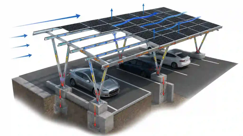
Solar carports and high-clearance PV structures are not simply ground mounts with taller posts.
The increased clearance and canopy geometry can create significant reactions in:
- Rails
- Beams
- Braces
- Columns
- Base plates
- Anchor bolts
- Concrete foundations
The system should also consider lateral stability from multiple wind directions.
For carports, the design must remain compatible with vehicle clearance, parking-bay geometry, drainage, and collision protection.
For agrivoltaic systems, agricultural machinery and operational clearance can drive even taller structures.
The higher structure can be entirely practical, but it should be engineered as a frame rather than extrapolated from a lower solar rack.
14. Trackers Add Dynamic Wind Behavior and Stow Strategy
A single-axis tracker can change its module angle.
That means wind design involves both the structure and its control strategy.
Depending on the tracker, engineers may need to consider:
- Operating-angle loads
- Stow-angle loads
- Dynamic response
- Torque tube behavior
- Bearings
- Drive assemblies
- Dampers
- Controller logic
- Weather sensing
- Power and communication
- Failure-mode position
DOE notes that tracker wind strategies can include engineered stow positions in high-wind conditions.
Research into tracker aerodynamics also shows that dynamic wind loading and structural instability remain active engineering topics, especially as modules become larger and more flexible.
A stow strategy does not mean the tracker becomes immune to wind.
The stow angle, trigger, structural assumptions, and control reliability are part of the engineered system.
15. Tilt Angle Is an Energy Decision and a Wind Decision
Increasing tilt can improve energy or snow-shedding performance in some projects, but it also changes the aerodynamic geometry.
DOE’s current installation guidance notes that lower tilt can reduce wind load, while steeper tilt can increase wind demand, creating a tradeoff for sites that also face winter-weather requirements.
That means tilt should not be finalized by energy modeling alone.
For fixed structures, compare:
- Energy yield
- Wind reactions
- Snow behavior
- Row spacing
- Ground or roof clearance
- Ballast or foundation demand
- Structural member size
- Land or roof utilization
The “best angle” is therefore a project decision, not only a solar-resource decision.
16. Wind Can Create a Zone-Specific BOM
A useful way to turn wind engineering into procurement information is to map the analysis into the bill of materials.
A project may use the same module throughout the array while changing selected mounting components by zone.
Possible zone-dependent changes can include:
- Roof attachment quantity
- Attachment spacing
- Ballast blocks
- Rail support spacing
- Brace quantity
- Fastener configuration
- Foundation size or embedment
- Module support points
- Edge-row details
This means the final BOM should match the final wind-layout drawing.
If the array layout changes, the BOM need to change.
If the building height changes, the design may need to change.
If a module is moved into a higher-demand edge area, its mounting configuration may need to change.
This is why the phrase “one kit fits the whole project” should be treated carefully on larger commercial and utility projects.
17. Installation Quality Can Determine Whether the Wind Design Works
Engineering calculations assume that the system is installed as designed.
Important field checks can include:
- Correct attachment locations
- Correct fasteners
- Correct embedment or structural connection
- Correct rail or beam spacing
- Correct clamp zones
- Correct bolt engagement
- Specified torque
- Locking hardware where required
- Required bracing
- Correct ballast location
- Correct foundation position
- No damaged or missing components
Wind-induced vibration can reveal weaknesses in poorly assembled joints.
DOE’s weather-vulnerability guidance includes real field examples of fastener loosening, insufficient mechanical attachment, and module-clamp failure. A 2025 federal storm-resilience review similarly reported inadequate frame stiffness and fastener strength among observed contributors to hurricane damage.
A design that depends on a specified clamp, bolt, or locking method should not be installed with an unreviewed substitute.
Quality control should therefore connect the engineering drawing, BOM, installation manual, and inspection record.
18. What Wind Information Should You Send a Solar Mounting Supplier?
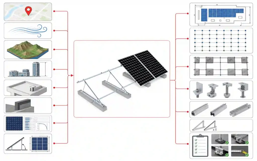
A supplier cannot prepare a meaningful wind-sensitive mounting configuration from “wind speed = 50 m/s” alone.
For a preliminary engineering review, provide as much of the following as possible:
| Project Input | Why It Matters |
|---|---|
| Project country and exact location | Identifies applicable wind data and project environment |
| Applicable design standard / code | Defines the wind-design framework |
| Design wind speed or required wind parameter | Establishes the basic wind input |
| Terrain / exposure category | Describes surrounding wind environment |
| Building height or array height | Affects wind demand |
| Roof dimensions and slope | Defines roof geometry |
| Parapet height | Can affect rooftop aerodynamics |
| Array location and setbacks | Identifies interior / perimeter / corner conditions |
| Module datasheet | Provides module dimensions, frame and mounting zones |
| Module layout | Defines array geometry and tributary loading |
| Tilt angle | Affects aerodynamic geometry |
| Roof structure / support spacing | Defines attachment load path |
| Foundation / soil information | Required for ground and carport reactions |
| Preferred mounting architecture | Rail, direct attach, ballasted, fixed tilt, tracker, etc. |
| Project drawings / photos | Helps confirm geometry and support conditions |
If the local engineer has already calculated project design pressures or support reactions, send those as well.
This creates a cleaner handoff than asking a supplier to infer the structural basis from a single wind-speed number.
19. What Should the Supplier Return?
For B2B procurement, wind information should also flow back from the supplier in a usable form.
Depending on scope, the supplier or engineering package may provide:
- Mounting layout
- Attachment spacing
- Rail or beam configuration
- Ballast layout
- Foundation reactions or requirements
- Bracing details
- Module support locations
- Fastener specification
- Torque requirements
- Bill of materials
- Material and finish information
- Installation instructions
- Project-specific design notes
- Required field verification
- Limitations or assumptions
The purchaser should verify that the quotation and production BOM match the same design revision.
If engineering assumptions change after quotation, the mounting quantities should be reviewed before manufacturing.
Common Mistakes in Solar Mounting Wind Design
Using Wind Speed as the Only Project Input
Wind speed does not describe building height, terrain, roof zone, tilt, array geometry, or attachment method.
Applying One Attachment Pattern to the Entire Roof
Interior, edge, and corner areas may not have the same demand.
Ignoring the Module Mounting Zone
The module frame is part of the structural load path.
Treating Ballast as a Simple Weight Calculation
Ballasted design also depends on array geometry, roof zones, friction, building height, and system aerodynamics.
Ignoring Lateral Bracing
Frames that resist vertical loads still need adequate lateral stability.
Using Generic Torque Values
Torque is connection-specific.
Substituting Fasteners Without Engineering Review
A different bolt, screw, washer, or clamp can change the joint behavior.
Ignoring Installation Tolerance
Mislocated roof attachments, piles, or posts can change the intended structural geometry.
Reusing an Old Wind Calculation After the Layout Changes
Changes to module size, tilt, array edge position, building geometry, or support spacing can affect wind demand.
Treating “High Wind” as a Product Category
A high wind PV mounting system is not defined by a marketing label alone.
It is a mounting configuration that has been designed and documented for the actual project wind conditions.
Common Questions About Wind Load and Solar Mounting
What is wind load on a solar mounting system?
Wind load is the structural demand created when wind pressure and suction act on PV modules and the supporting racking. The resulting forces are transferred through clamps, rails, brackets, frames, attachments, or foundations.
Is wind uplift usually important for rooftop solar?
Yes. Uplift is a major design consideration because wind can create negative pressure that tries to lift modules and racking away from the roof.
Are wind loads higher at roof edges and corners?
They can be. Building-edge and corner aerodynamics can create more demanding local suction conditions than interior roof areas, so rooftop PV layouts and attachment or ballast patterns may need zone-specific treatment.
Does a higher building need stronger solar mounting?
Not automatically in every case, but building height is an important wind-design input and can increase the demand on the mounting system depending on the applicable design method and geometry.
Does increasing solar panel tilt increase wind load?
Tilt changes the aerodynamic geometry and can increase wind demand in many configurations. The final effect should be evaluated together with site wind, array type, height, and structural design.
Does railless mounting reduce wind load?
Not inherently.
Removing rails changes the load path. Wind still has to be transferred through the module, direct mounts, roof attachments, and building structure.
Does adding more roof attachments always solve a wind problem?
Not by itself.
Attachment quantity is only one variable. Rail capacity, module support, fasteners, roof structure, spacing, waterproofing, and the complete load path still need to be checked.
Are ballasted systems suitable for high-wind roofs?
They can be suitable when the engineered ballast, roof load capacity, friction, array geometry, roof zones, and project requirements support the design. In some high-wind conditions, strategic mechanical attachments or hybrid designs may be preferable.
How does wind affect ground-mounted solar?
Wind creates uplift, lateral loads, overturning, frame torsion, and foundation reactions. The structure, bracing, posts, piles, screws, or concrete foundations should be designed as one load path.
Why do solar mounting bolts loosen in wind?
Repeated vibration, inadequate preload, unsuitable joint design, installation errors, or joint relaxation can contribute to loosening. DOE has documented wind-induced fastener loosening and related mounting vulnerabilities in operating PV systems.
What wind data is needed for a solar mounting quotation?
Provide project location, applicable standard, wind speed, snow load, terrain/exposure, building or array height, roof/site geometry, module data, solar panel orientation, tilt, layout, solar mount system type, foundation type and engineering drawings.
Treat Wind Load as a System Requirement
Wind load does not belong to one component.
It begins with the site and passes through the entire mounting system.
Site Wind → Aerodynamics → Module → Clamp → Rail / Frame → Attachment / Foundation → Supporting Structure
Every link matters.
For procurement and preliminary system selection, the most useful practice is to provide the project wind inputs early and keep the mounting layout, structural design, BOM, and installation documentation on the same revision.
Explore Solar Mounting Systems for roof, ground, carport, agrivoltaic, and related mounting options.
For rooftop projects, see Roof Solar Mounting Systems.
For ground-mounted projects, see Ground Solar Mounting Systems.
For a project-specific discussion, send your wind load requirements together with the module datasheet, roof or site layout, height, terrain/exposure information, tilt, and available structural drawings.
References & Technical Sources
- U.S. Department of Energy — Severe Weather Resilience in Solar Photovoltaic System Design
- U.S. Department of Energy — Life Cycle of Photovoltaic Systems: Install and Commission a Photovoltaic System
- U.S. Department of Energy — Solar Photovoltaic System Design Basics
- Pacific Northwest National Laboratory / Building America Solution Center — Roof Anchor System for Solar Panels
- U.S. Department of Energy — PV System Owner’s Guide to Identifying, Assessing, and Addressing Weather Vulnerabilities, Risks, and Impacts
- U.S. Department of Energy — General Services Administration Explores Solar Photovoltaic Storm Resilience After Hurricane Damage

Sales Manager at Easy Solar Solar Mounting Systems. With over 1o years of experience in the solar industry, I specialize in providing reliable andcost-effective mounting solutions for distributors, installers, and EPC companies. Experienced in intemational sales and commited to building long-term partnerships worldwide.