
Solar Rail Splice Kits
Easy Solar supplies solar rail splice kits for joining compatible aluminum PV mounting rails in rooftop, ground-mount and carport systems. Internal, external and drawing-based rail connectors can be matched according to rail geometry, connection hardware, installation method and project requirements.
- Internal & External Splices
- Rail-Specific Compatibility
- Aluminum Connector Profiles
- Standard & Custom Options
- OEM & Bulk Supply
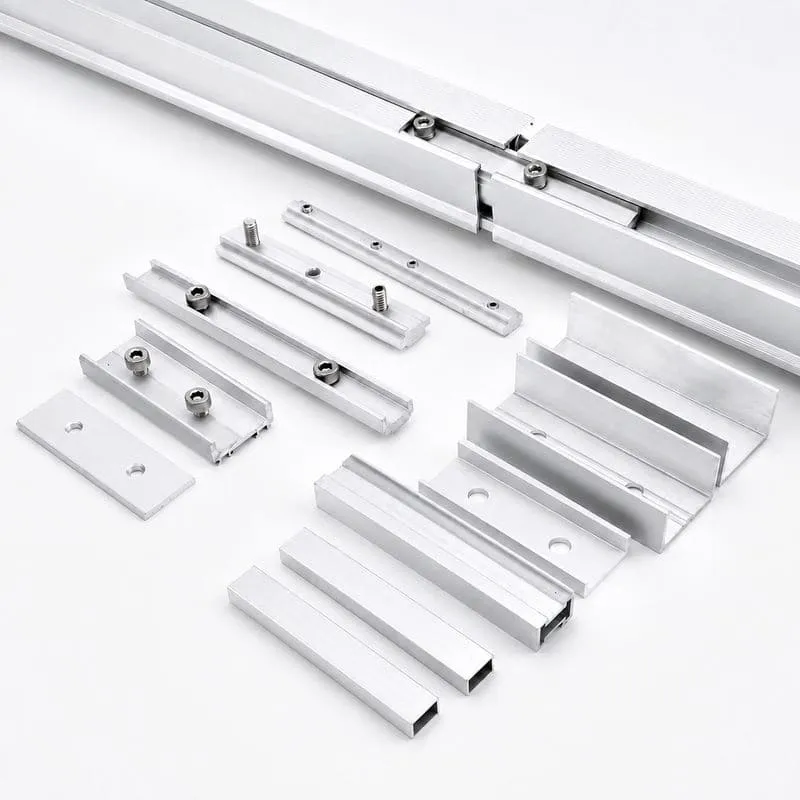
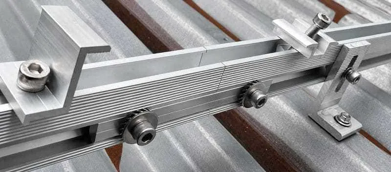
Solar Rail Splice Connectors for PV Mounting Systems
Solar rail splice kits connect two compatible mounting rail sections where a continuous module row is longer than one transport or production rail length. A correctly matched splice helps maintain rail alignment and provides the specified rail-to-rail connection for the mounting system.
Easy Solar supplies aluminum solar rail splice connectors for professional PV projects. The splice profile, engagement length, fastener arrangement, finish and connection method should be selected according to the rail section, system drawing and project installation requirements.
- Rail splice kits for rooftop, ground-mount and carport PV systems
- Internal, external and project-specific connection options
- Compatibility review based on rail profile and connector interface
- Custom cutting, holes, fasteners, packaging and OEM project supply
Solar Rail Splice Types and Connection Options
Select the splice according to the rail cross-section, connector position, available channel, fastener method and installation requirements of the complete PV mounting system.
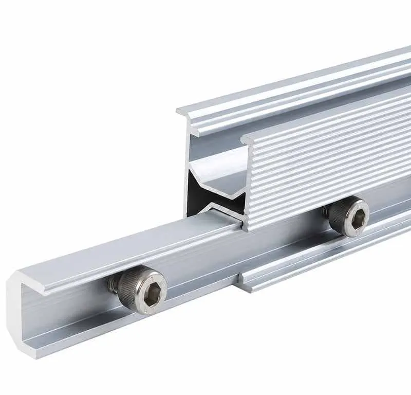
Internal Solar Rail Splice
Connector profile positioned inside compatible rail cavities to join adjacent rail sections while keeping the outer rail surface compact.
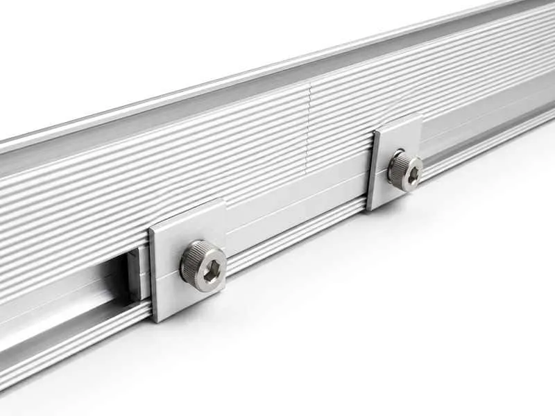
External Solar Rail Splice
External plate or connector fixed to compatible rail channels with bolts or fastening hardware according to the selected mounting system.
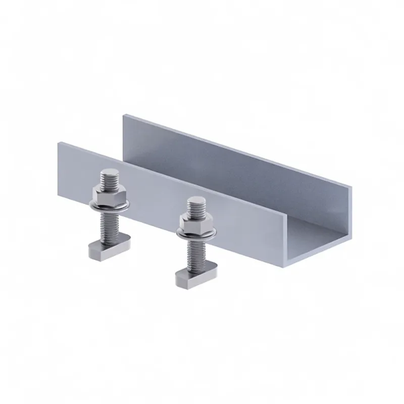
Custom Rail Splice Profiles
Drawing-based connector profiles, holes, lengths and fastening arrangements for existing or project-specific aluminum solar rails.
Match the Splice to Your Solar Rail Profile
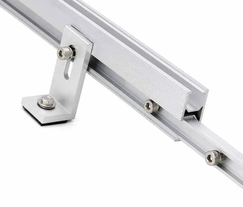
Solar rail splice connectors are not universally interchangeable. The internal cavity, side slot, connector width, engagement area, wall geometry and fastener position must match the selected rail profile.
For accurate matching, provide a rail cross-section drawing, dimensions or sample photo. Easy Solar can review an existing rail interface or discuss a connector profile for a new OEM mounting system.
- Rail width, height and internal cavity dimensions
- Top, side or bottom channel geometry
- Internal or external splice position
- Fastener type, hole spacing and tightening method
- Required connector length and engagement area
| Rail Cross-Section | Confirm overall rail width, height, internal cavity, wall geometry and available splice interface |
|---|---|
| Connector Type | Internal, external or drawing-based connector according to the selected rail and installation system |
| Engagement Length | Selected according to splice design, rail geometry and system-specific installation requirements |
| Fastener Interface | Bolts, screws, T-bolts or other hardware matched to the rail slot and connector design where applicable |
| Surface Finish | Mill finish, anodized or project-specific finish according to product specification and buyer requirements |
| Project Confirmation | Final dimensions, installation position and hardware should be confirmed against the approved drawing |
What Does a Solar Rail Splice Do?
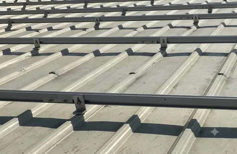
Long module rows often require two or more rail sections to be joined on site. A compatible splice creates the intended connection between rail sections and helps keep the mounting line aligned during installation.
Splice function depends on the rail system. Structural behavior, allowed splice position, thermal movement and bonding requirements should therefore be reviewed according to the project drawing and system documentation.
- Join transport-length or production-length rail sections on site
- Maintain the intended alignment between adjacent rails
- Coordinate with the selected rail slots, fasteners and support layout
- Follow system-specific structural, expansion and bonding requirements
How to Install a Solar Rail Splice
The exact installation method depends on the rail profile and splice design. Use the approved drawing, fastener specification and project installation instructions for final assembly.
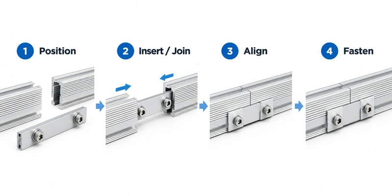
Position the Splice
Insert or place the connector at the specified position on the first compatible rail section.
Join the Second Rail
Bring the second rail into the connector while maintaining the required alignment and joint position.
Align the Rail Sections
Check rail line, splice engagement and any required joint or expansion gap before final fastening.
Secure the Connection
Tighten the specified hardware according to the approved installation drawing and torque requirements.
Structural, Expansion and Bonding Considerations
Rail splice selection should be reviewed as part of the complete PV mounting system rather than as an isolated accessory.
Structural Connection
Confirm whether the selected splice is intended to provide a structural rail connection and where it may be located relative to supports, cantilevers and module zones.
Thermal Expansion
Long aluminum rail rows may require expansion planning. Rail length, splice arrangement and joint gaps should follow the applicable system and project documentation.
Electrical Bonding
Mechanical connection does not automatically confirm electrical bonding. Verify whether the selected system uses a bonding splice or requires separate grounding and bonding components.
Rail Splice Kits for Roof, Ground and Carport Solar Systems
Connector selection should follow the rail system, module row length, support layout and installation method used in the project.
Roof Solar Mounting
Rail connectors for compatible rooftop PV rails used with hooks, L feet, brackets and related roof attachments.
View Roof Systems →Ground Solar Mounting
Rail-to-rail connector options for compatible ground-mounted PV support and module rail configurations.
View Ground Systems →Solar Carport Systems
Splice options for compatible carport mounting rails and selected long-row canopy rail arrangements.
View Carport Systems →Solar Mounting Rails
Match the splice with the exact rail profile, cavity, channel, fastener interface and system geometry.
View Mounting Rails →How to Select the Correct Solar Rail Splice
Provide complete rail and project information so the connector profile, engagement, fastening method and packaging can be reviewed together.
Rail Profile
Provide the rail cross-section drawing, overall dimensions, cavity and available connection channels.
Connection Method
Confirm whether the system uses an internal, external, slide-in or bolted rail splice connection.
Project Requirements
Provide rail lengths, module row layout, support arrangement and applicable structural or expansion requirements.
Supply Details
Confirm quantity, fastener requirements, finish, packaging, labels and delivery plan.
Custom Solar Rail Splice Connector Manufacturing
Easy Solar supports B2B buyers who need standard rail splice kits or drawing-based aluminum connector profiles matched to existing solar mounting rails.
Custom work may include connector profile review, extrusion, cutting, drilling, punching, surface treatment, fastener matching, labels and project packaging. Final production details depend on the approved drawing, order quantity and technical confirmation.
- Drawing-based or sample-based rail splice discussion
- Custom connector profile, length, holes and fastener arrangement
- Anodizing and project-specific surface finish options
- OEM labels, carton packing and distributor packaging
- Rail, splice, clamp and fastener package coordination
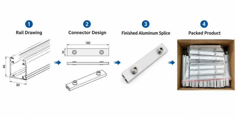
Solar Rail Splice Manufacturer and Supplier
Easy Solar supports installers, EPC contractors, distributors and OEM buyers with aluminum connector processing, component matching and export-ready project supply.
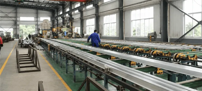
Profile Manufacturing
Standard and custom aluminum rail splice profiles can be discussed according to rail drawings, dimensions, application and production quantity.

Cutting & Processing
Cutting, drilling, punching, surface treatment and inspection options support project-specific installation and packaging requirements.
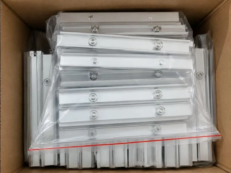
Project Packaging
Rail splice kits can be packed according to connector type, fastener set, distributor labeling and project delivery plan.
Solar Rail Splice Kit Specifications
Final connector specifications should be confirmed according to the rail profile, mounting system, connection hardware, installation method and approved project drawing.
| Product Name | Solar Rail Splice Kits / Solar Rail Splice Connector / PV Rail Connector |
|---|---|
| Applications | Roof solar mounting systems, ground-mounted PV systems, solar carports and compatible project-specific rail systems |
| Connector Type | Internal, external or project-specific connector according to the rail profile and installation design |
| Material | Aluminum alloy or project-specific material according to connector design and buyer specification |
| Fasteners | Matched stainless steel or project-specific fastening hardware where required by the selected connector design |
| Surface Finish | Anodized, mill finish or project-specific surface treatment according to product and installation environment |
| Length | Standard or customized connector length according to rail geometry, system design and approved drawing |
| Rail Compatibility | Matched to the exact rail cross-section, cavity, side slot, fastener interface and connection method |
| Customization | Profile dimensions, connector length, holes, fasteners, surface treatment, labels and packaging available upon discussion |
| Buyer Type | EPC contractors, installers, distributors, wholesalers, OEM customers and PV mounting system brands |
Replace model-specific fields with your confirmed production data before publishing individual SKU specifications.
Request a Solar Rail Splice Kit Quote
Send Easy Solar your rail cross-section, dimensions, connector requirement, quantity and project details. Our team can review the rail-to-splice interface and prepare a factory-direct quotation for a standard or drawing-based connector option.
- Rail cross-section drawing or sample photo
- Rail width, height, cavity and slot dimensions
- Internal or external connector requirement
- Required splice length and fastener arrangement
- Mounting system and project application
- Material and finish requirements
- Quantity, packaging and delivery plan
Solar Rail Splice Kits FAQ
Common questions from solar installers, EPC contractors, distributors and PV mounting system buyers.
What is a solar rail splice kit?
A solar rail splice kit is a connector used to join two compatible PV mounting rail sections. Depending on the rail system, the connector may be installed inside the rail cavity or fixed externally.
Can one solar rail splice fit different mounting rails?
Not necessarily. Compatibility depends on the rail cross-section, internal cavity, side or bottom slot, connector engagement, fastener position and installation design. The rail drawing should be checked before ordering.
What is the difference between an internal and external rail splice?
An internal splice is positioned inside a compatible rail cavity, while an external splice is fixed to the outside of the rail with compatible fastening hardware. The correct type depends on the rail design.
How do I select the correct solar rail connector?
Please provide the rail cross-section drawing, dimensions, splice position, connection method, required connector length, fastener details and project application for technical review.
Does a solar rail splice provide structural connection?
Structural function depends on the rail and splice system. The allowed splice position, support layout and connection capacity should be confirmed from the applicable system drawing and engineering requirements.
Does a rail splice provide electrical bonding?
Not every mechanical rail splice is a bonding component. Confirm whether the selected mounting system uses a bonding splice or requires separate grounding and bonding hardware.
Do long solar rails need expansion gaps at splice locations?
Long aluminum rail rows may require thermal expansion planning. Joint gaps, maximum continuous rail lengths and expansion arrangements should follow the selected system and project documentation.
Can you manufacture a splice for my existing rail profile?
Yes. Drawing-based connector profiles, lengths, holes, fastening interfaces, finishes and packaging can be discussed based on the existing rail drawing or sample and the required order quantity.
What information is needed for a rail splice quotation?
Please provide the rail drawing or sample, profile dimensions, connection method, connector length, fastener requirements, material and finish, quantity, packaging and delivery plan.