
Ground Mount Solar Racking: Foundations, Site Design & Installation Guide
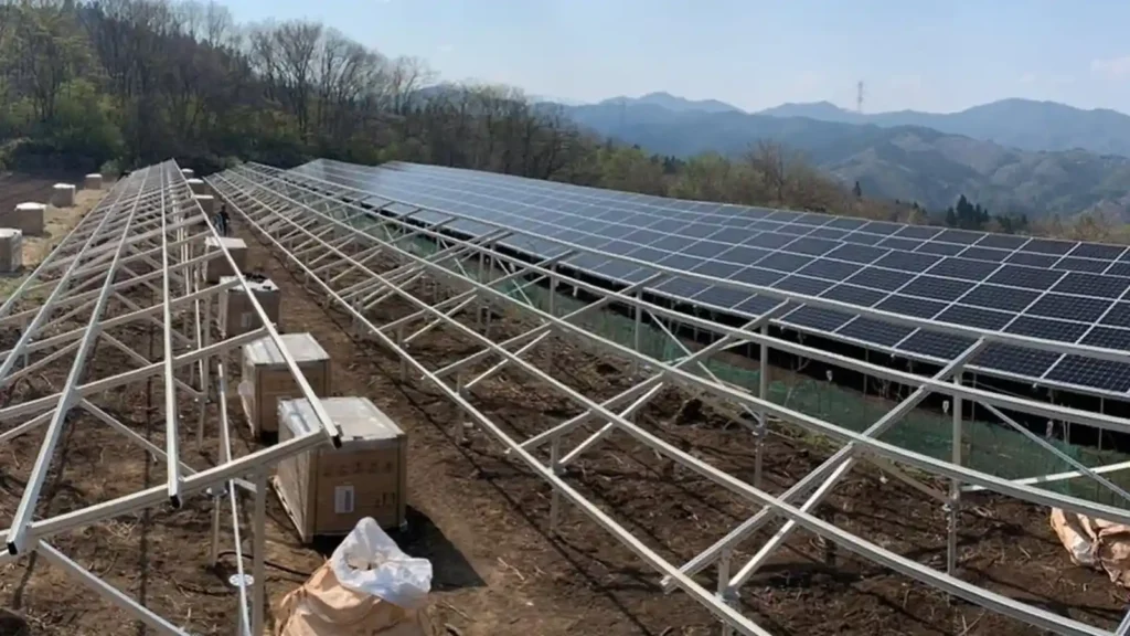
Ground mount solar racking should be selected from the site downward—not from a generic product drawing. The soil and terrain help determine the foundation; the module layout and environmental loads help determine the frame; and the installation method must match the equipment, access and construction sequence available on site.
This guide focuses mainly on fixed-tilt ground-mounted PV and explains how site information, foundations, structural configuration, terrain, wind, snow, drainage and installation conditions influence the final racking system.
Quick Answer: What Determines a Ground-Mount Solar
Racking System?
A ground-mount solar racking system is determined by more than whether the array is “fixed tilt” or “ground screw mounted.” The final configuration should be based on site and soil conditions, module dimensions, table geometry, tilt, row spacing, wind and snow design inputs, ground clearance, corrosion environment, drainage, construction access and maintenance requirements.
The most important sequence is: site and soil review → foundation concept → structural configuration → verification → installation. Foundation depth, screw size, pile section, ballast weight, tilt and row spacing should not be copied from another project without site-specific review.
Ground Mount Solar Racking at a Glance
| Design Question | Typical Options | What Should Drive the Decision? |
| Structure type | Fixed tilt; tracker; special/adjustable configuration | Project scale, terrain, energy strategy, O&M |
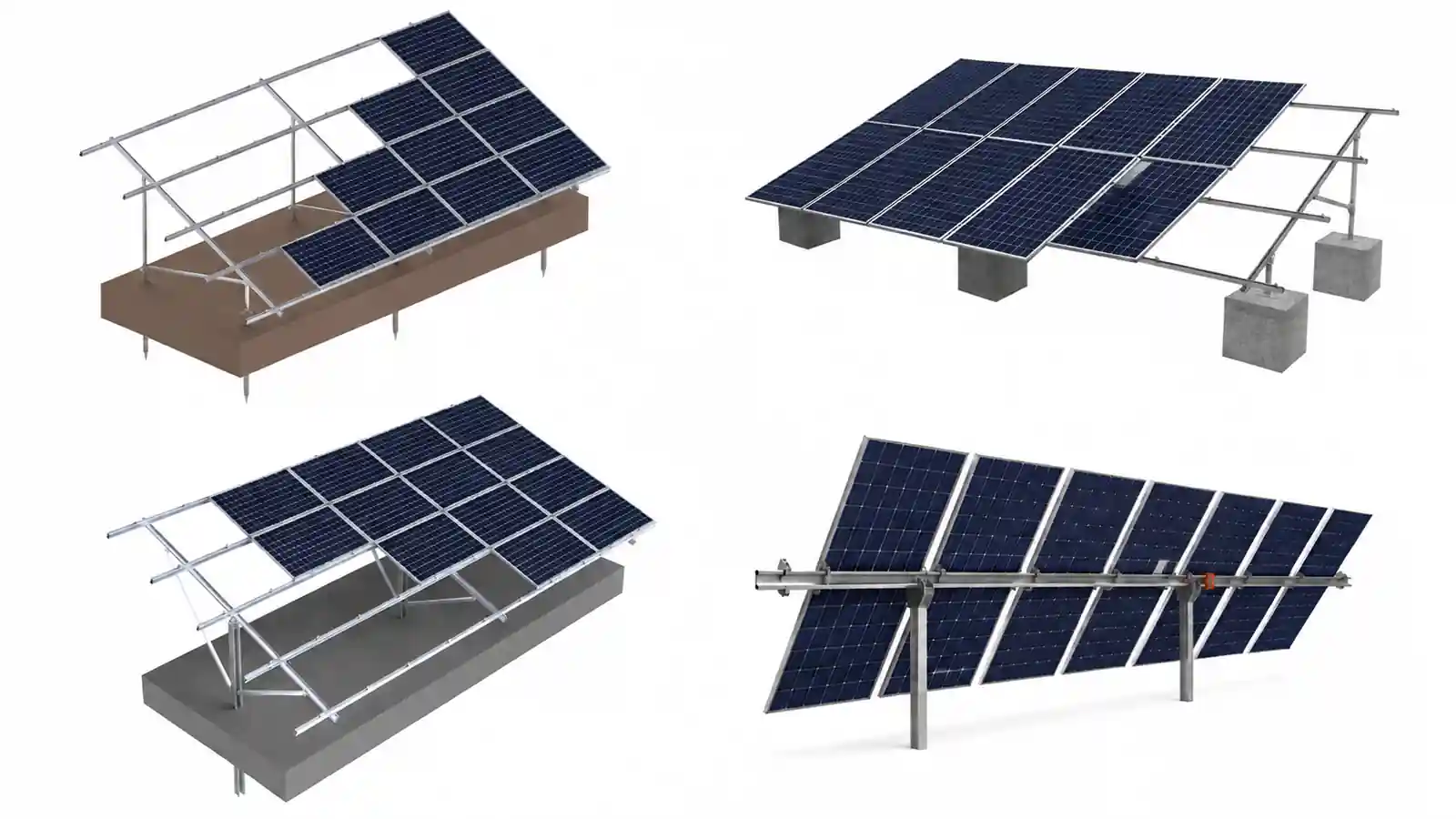
| Foundation | Driven pile; ground screw; concrete; selected ballast | Soil, groundwater, rock, frost, structural reactions, equipment |
| Module table | Portrait or landscape; different table sizes | Module dimensions, clamp zones, span, site geometry |
| Tilt | Project-specific fixed angle or tracking movement | Energy model, wind, snow, land use, ground clearance |
| Row spacing / GCR | Project-specific | Shading, land use, access, drainage, vegetation, snow |
| Materials | Galvanized/coated steel, aluminum, stainless hardware | Structural role, corrosion environment, logistics |
| Installation | Driven, screwed, cast, assembled, aligned, clamped | Foundation type, terrain, equipment, pre-assembly and tolerance |
How Ground Mount Racking Transfers Loads?
Unlike rooftop PV, ground-mounted racking cannot rely on an existing building as its primary supporting structure. It must create a complete structural load path from the modules into the foundation and soil.
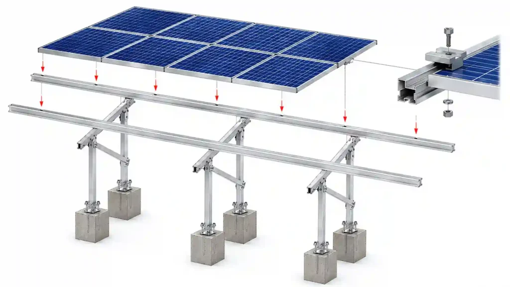
This is why the foundation is not a separate procurement item. A strong rail cannot compensate for an inadequate foundation, and a strong foundation cannot compensate for weak module clamps, frame connections or bracing.
Fixed-Tilt vs Tracking Ground Mount Systems
Fixed-Tilt Ground Mount Racking
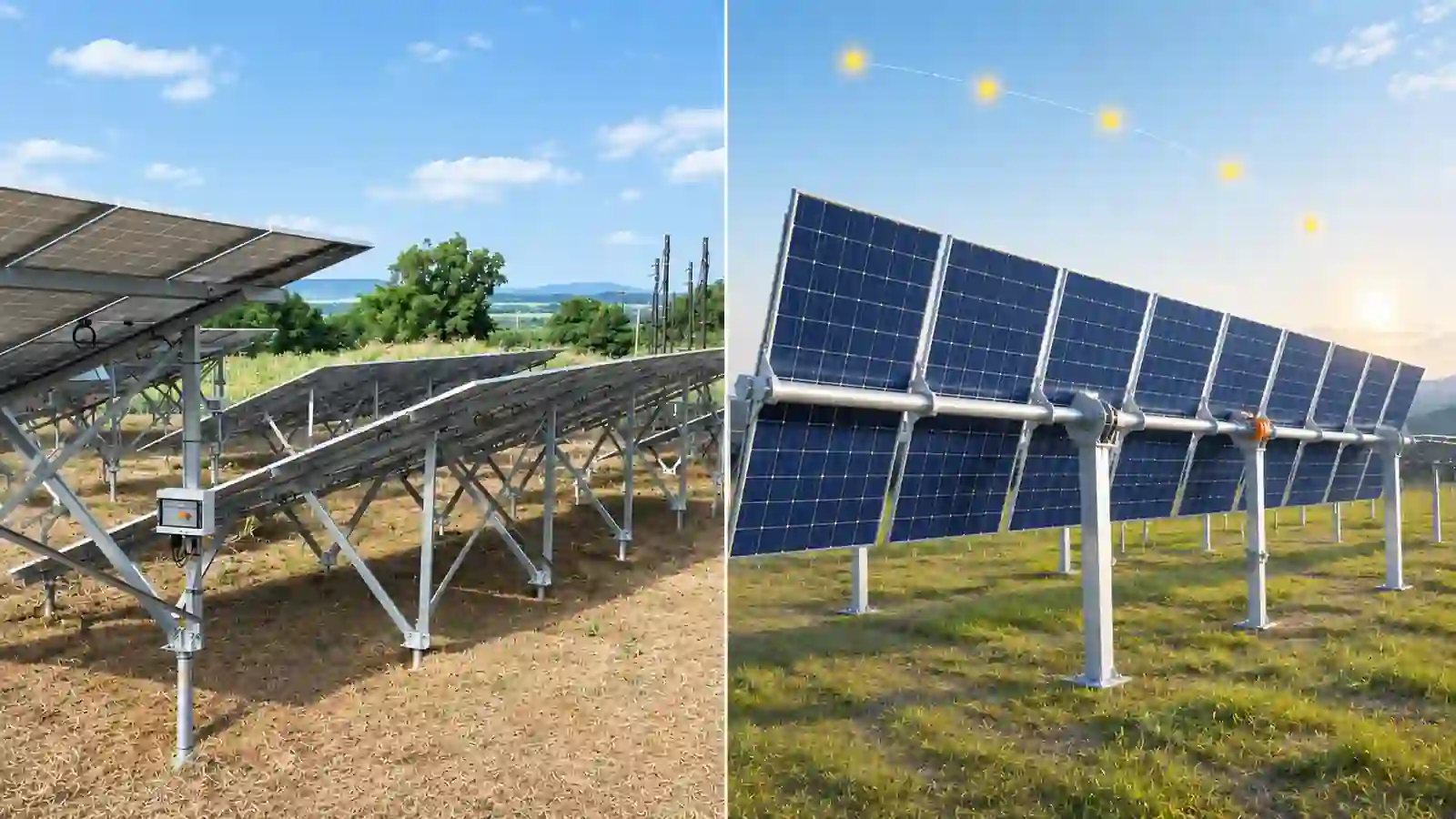
A fixed-tilt system holds the PV modules at a designed angle throughout normal operation. Typical structural elements include foundations, posts, main beams or rafters, bracing, rails or purlins, module clamps, structural fasteners and grounding components.
Fixed tilt has fewer moving mechanical components than a tracker. It can be suitable where structural simplicity, predictable construction and lower mechanical maintenance are priorities. This guide therefore focuses primarily on fixed-tilt ground-mount racking.
Single-Axis Tracking
A single-axis tracker rotates module rows during the day and adds components such as torque tubes, bearings, drive units, motors or actuators, controllers and tracker-specific supports. Tracking can increase energy capture in suitable projects, but it also changes foundation reactions, terrain tolerance, commissioning, stow strategy and O&M.
The choice between fixed tilt and tracking should be made at project level, not from energy yield alone.
Start with Site and Soil Information
Project location and available land boundary
Ground-mount design should begin with site information before the final racking and foundation are selected. The site defines constraints that cannot be solved later by changing only a rail or post.
- Project location and available land boundary
- Topographic survey and slope information
- Soil or geotechnical information
- Groundwater and frost conditions where applicable
- Rock, buried obstructions and existing utilities
- Drainage paths, flood risk and erosion conditions
- Vegetation and planned ground cover
- Access roads and installation-equipment access
- Environmental or subsurface restrictions
DOE ground-mounted PV guidance likewise treats foundation, topography and soil as project-specific design considerations. The foundation should therefore follow the site—not the other way around.
Ground Mount Foundation Types
Driven Pile Foundations
Driven piles are steel structural members installed with impact or vibratory equipment. They can support efficient, repetitive installation on large sites where the soil and access are suitable.
Key checks include soil profile, refusal risk, rock or buried obstructions, embedment, compression capacity, uplift capacity, lateral resistance, corrosion allowance and installation tolerance. Driven piles should not be selected only because repetitive installation can be efficient; shallow rock, weak layers, obstructions or difficult access can change the foundation strategy.
Ground Screw Foundations
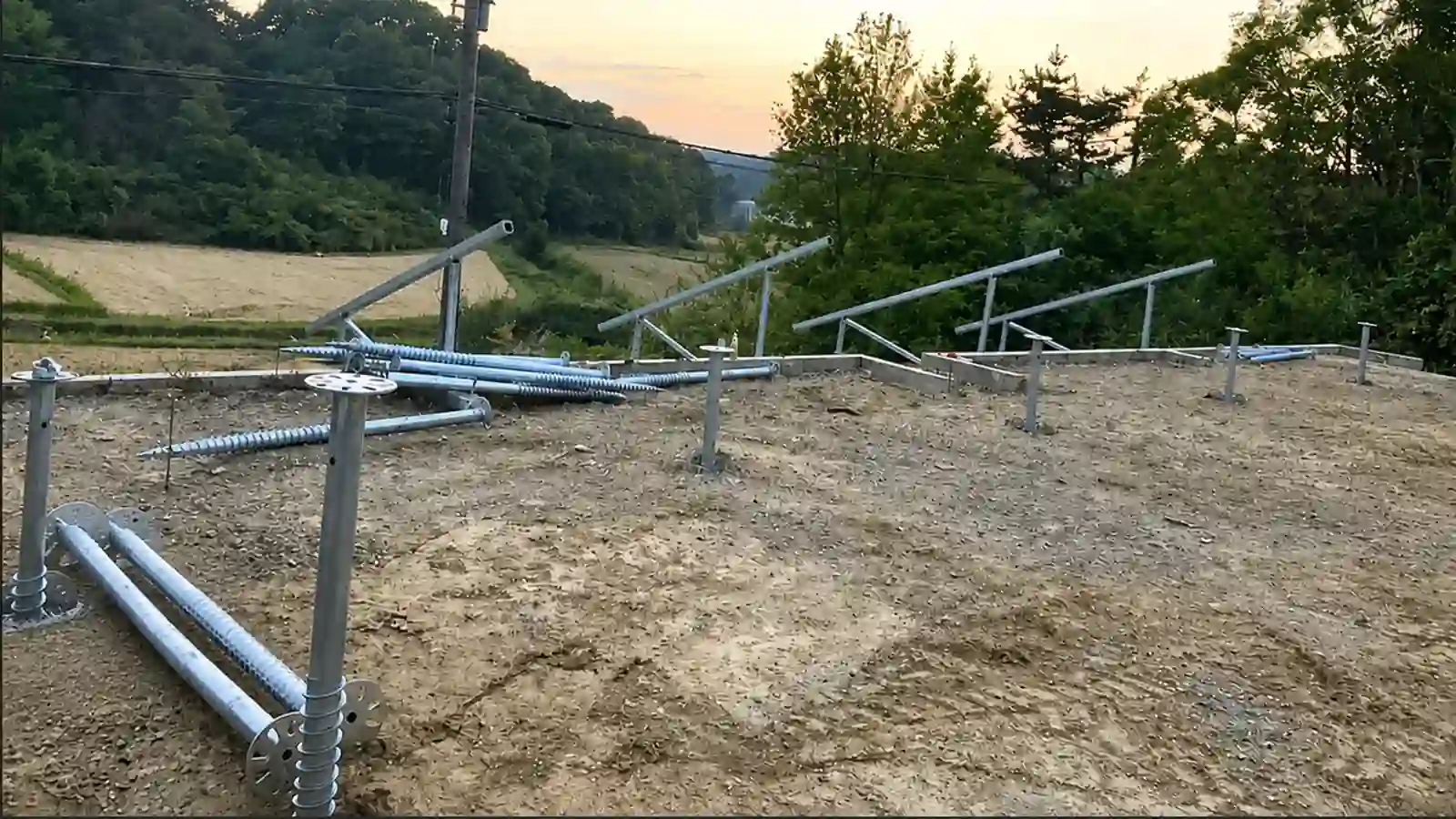
Ground screws are steel foundations installed by rotating the screw into the soil. They can reduce cast-in-place concrete work and can be useful where installation speed, reversibility or variable terrain are important.
Their suitability still depends on screw geometry, soil type, installation torque, embedment, uplift and lateral requirements, groundwater, frost and corrosion. A ground screw is not a universal solution for rocky ground; some conditions may require pre-drilling, a different screw concept or another foundation type.
Concrete Foundations
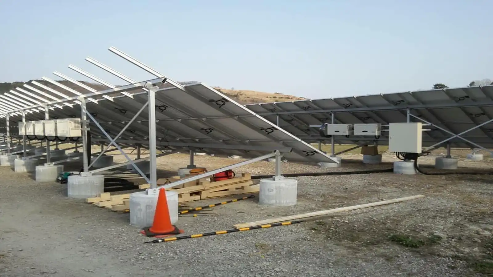
Concrete foundation concepts can include cast-in-place piers, isolated footings, grade-supported bases, precast bases and base plates with anchor bolts. Concrete may be useful when piles or screws are impractical or when the structural concept requires a different load-distribution strategy.
Tradeoffs can include excavation, reinforcement, concrete delivery, formwork, curing time, civil-work scope and more permanent site disturbance. Concrete is not automatically the safest or best foundation; it is one option to be evaluated against the site and structural reactions.
Ballasted / Non-Penetrating Ground Foundations
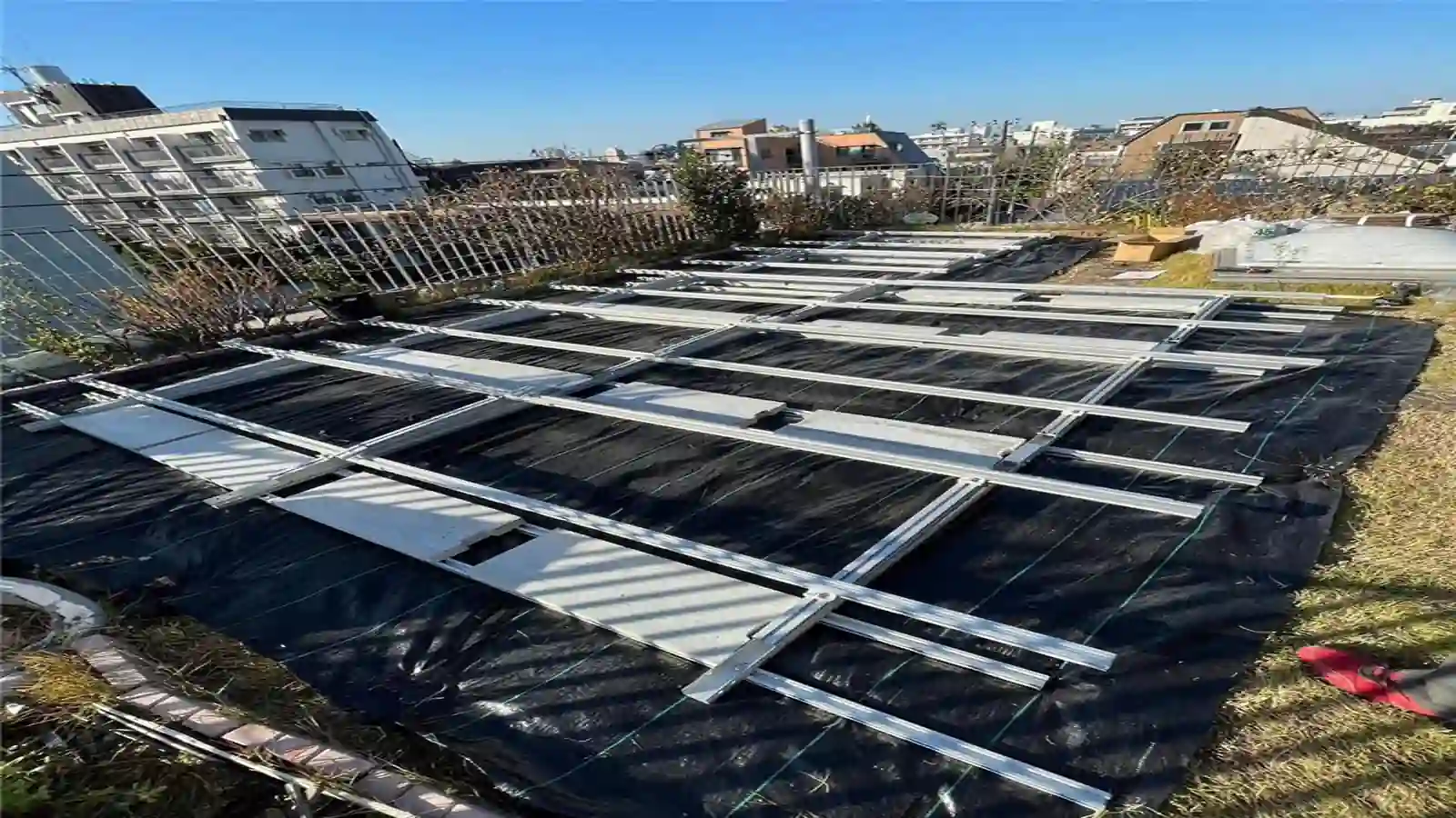
Selected restricted sites may use above-ground ballast rather than penetrating the soil. Possible applications include landfills, brownfields or sites with subsurface restrictions.
Ballasted ground mounting introduces its own checks for total weight, sliding, overturning, settlement, drainage, bearing conditions and site preparation. It should be treated as a specialized foundation concept—not as a way to avoid site assessment.
Ground Mount Foundation Comparison
| Foundation Type | Potential Advantage | Main Site Question | Typical Constraint |
| Driven pile | Repeatable installation on suitable large sites | Can the soil develop required capacity without refusal? | Rock, obstructions, tolerance |
| Ground screw | Reduced cast-in-place concrete; adaptable installation | Can the screw be installed and develop required uplift/lateral capacity? | Rock, torque and soil limitations |
| Concrete pier / footing | Flexible structural and anchoring concept | Is the soil suitable and is the civil scope practical? | Excavation, curing, labor, permanence |
| Ballasted ground base | Limits or avoids ground penetration | Can the site support ballast and resist sliding/overturning? | Weight, settlement, site restrictions |
This comparison is intentionally qualitative. Foundation depth, pile section, ground-screw geometry, concrete size and ballast weight should remain project-specific.
Foundation Verification: Geotechnical Investigation & Field Testing
Selecting a foundation family is not the same as confirming the final foundation specification. Geotechnical information helps the project understand soil layers, groundwater, rock, frost and other conditions that may affect compression, uplift, lateral resistance, settlement or installation feasibility.
Depending on the project, field verification may also be required. Pile or ground-screw testing can be used to confirm whether the proposed foundation can achieve the required performance in the actual site conditions. The appropriate test method, sample size and acceptance criteria should be defined by the responsible project engineer or geotechnical/structural team.
For procurement, this means a supplier can discuss a preliminary foundation concept before all testing is complete, but the final embedment, screw geometry or foundation size should not be treated as confirmed until the required project data and verification are available.
Published geotechnical research from the American Society of Civil Engineers (ASCE) has also compared full-scale uplift performance of multiple solar foundation types across different soil conditions. The engineering lesson is the same: foundation behavior should be verified against the actual site rather than assumed from a generic foundation family or catalog dimension.
Real Engineering Example: One Site, Multiple Structural Configurations
Historical Easy Solar Engineering Project — 316 kW Ground-Mounted PV, Japan
A historical Easy Solar ground-mount project in Japan demonstrates why “ground screw system” does not define the final structure by itself.
Project Inputs
| Project Input | Historical Project Data |
| Application | Fixed-tilt ground-mounted PV |
| Capacity | Approximately 316 kW |
| PV module size | 1684 × 1002 × 35 mm |
| Foundation concept | Ground screws |
| Tilt configurations | 10°, 20° and 30° |
| Wind design input | 30 m/s |
| Snow condition | 35 cm |
| Design reference | JIS C 8955:2017 |
| Table arrangement | Multiple table sizes/configurations across the same site |
Why the Structure Was Not Identical Across the Site
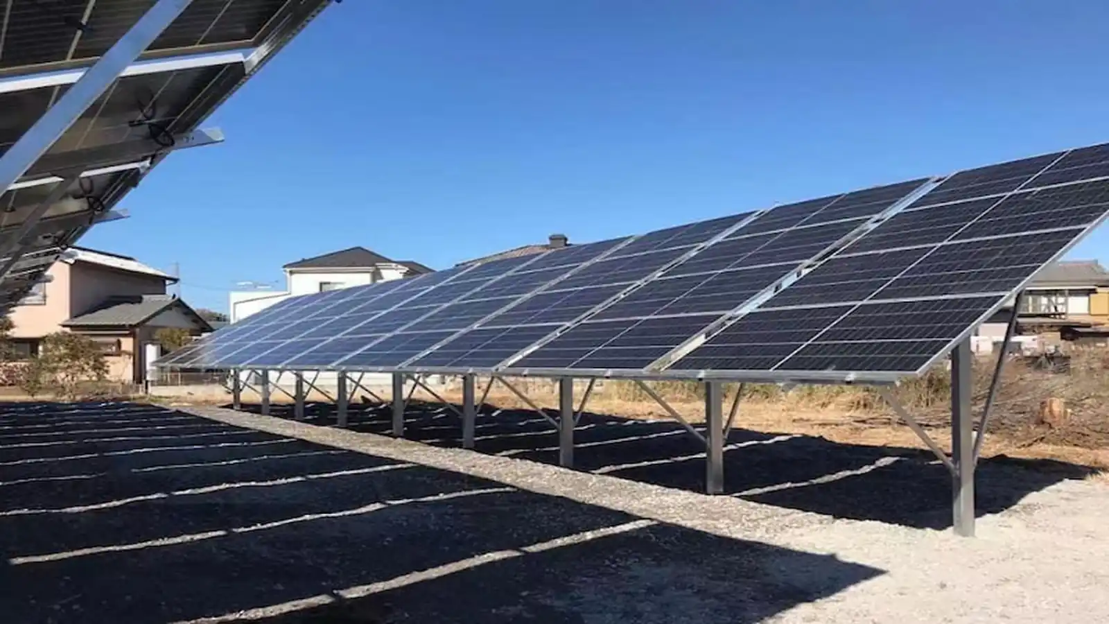
The project used several module-table configurations rather than one identical table repeated everywhere. Different tilt angles and table sizes changed the frame geometry, support arrangement and foundation layout even though the overall project remained a fixed-tilt ground-mounted system using ground screws.
The project drawings also stated that the final foundation specification should be determined according to geotechnical investigation or on-site testing. This is a practical example of the difference between choosing a foundation concept and verifying a final foundation design.
Examples of Table Variation Within the Same Project
| Project Evidence | Examples from the Historical Drawings |
| Smaller table configurations | 2×2, 2×3, 2×4 |
| Medium table configurations | 4×4, 4×7, 4×8 |
| Larger table configurations | 4×9, 4×10, 4×12, 5×9 |
| Tilt configurations | 10°, 20° and 30° |
These configurations came from the same historical ground-mounted project rather than from separate catalog examples. The variation shows how one site can require different table geometries even when the module family, general foundation concept and project location remain the same
Engineering Takeaway
“Ground mount” and “ground screw” describe only part of the system. Module dimensions, table size, tilt, wind, snow, site geometry and foundation verification can still change the final structural configuration within a single project.
Terrain, Tilt, Row Spacing & GCR
Terrain and Slope
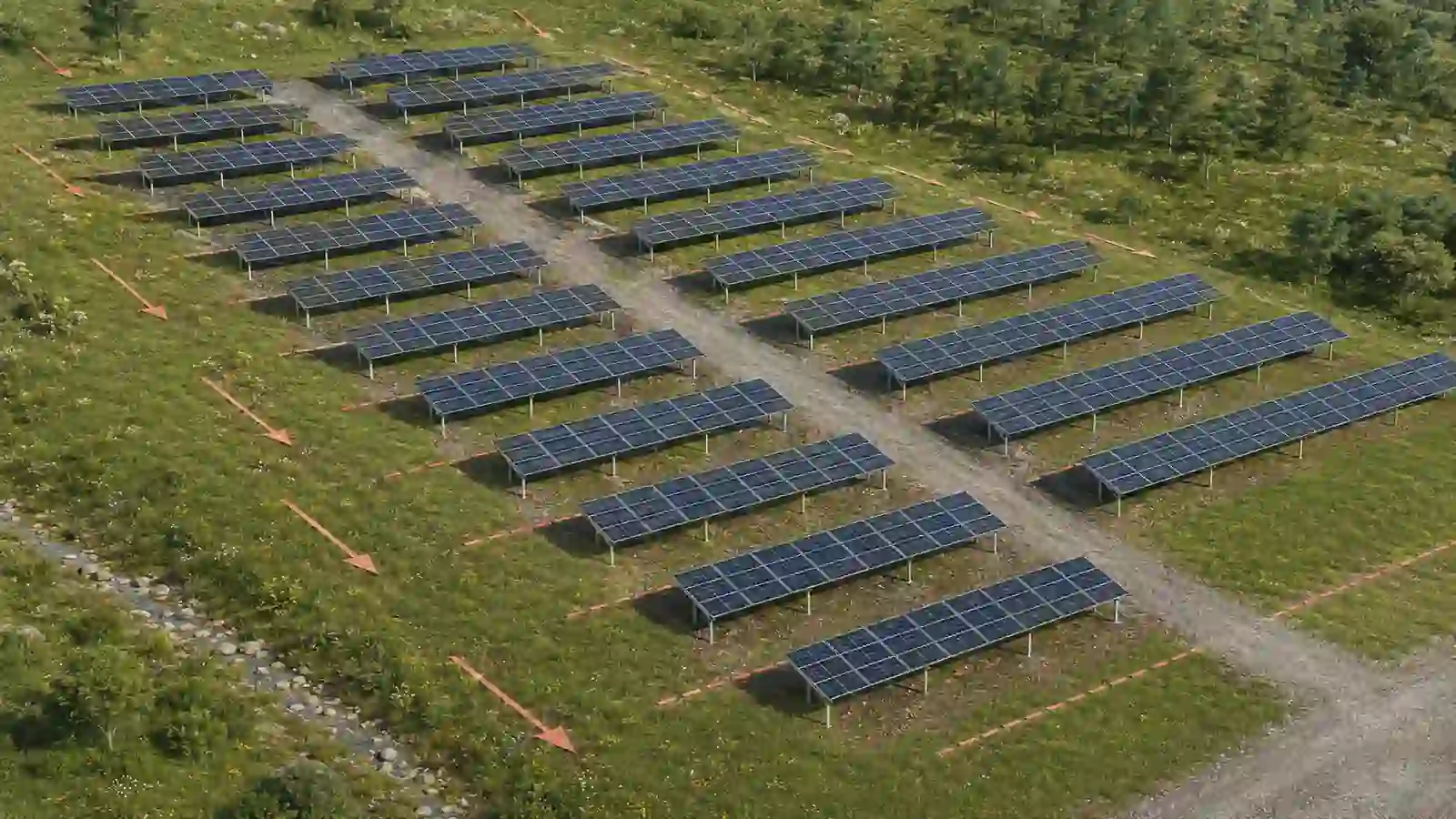
Real ground-mount sites can include slopes, elevation changes, drainage channels, depressions and uneven ground. Terrain can affect post length, foundation elevation, beam connection height, row alignment, ground clearance, installation tolerance, equipment access, drainage, erosion and cable routing.
The structure should not be forced into a perfectly level geometry if that creates excessive grading or impractical post heights. Depending on the system, the project may follow terrain, use stepped rows, vary post lengths, adjust foundation elevations or selectively grade part of the site.
Tilt Angle and Orientation
There is no universal “best” tilt for every fixed-tilt ground project. Tilt is normally coordinated with the energy model, project latitude, module technology, wind and snow requirements, ground clearance, land availability, row spacing and construction cost.
Row Spacing and Ground Coverage Ratio
Row spacing is a tradeoff between energy performance, land use, maintenance and civil design. Tighter spacing can increase installed density but may increase inter-row shading or reduce access. Wider spacing can reduce shading but increase land, trenching and maintenance distances.
Ground Coverage Ratio (GCR) is one way to describe array density. A higher GCR generally means denser land use; a lower GCR generally means more space between rows. The appropriate value should come from the project energy, civil, structural and land-use strategy rather than a fixed number copied from another site.
Environmental Loads: Wind, Snow & Frost
Wind
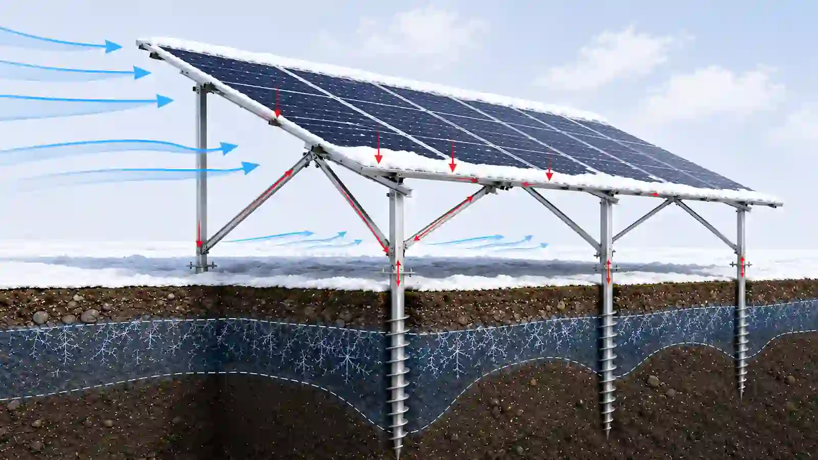
Ground-mounted arrays are open structures exposed to wind from multiple directions. Wind can create uplift, downward pressure, lateral force, frame torsion, foundation overturning reactions and loads in module clamps and fastened joints.
DOE severe-weather guidance emphasizes robust racking, lateral bracing where required and reliable critical fastened joints. The complete load path should therefore be reviewed from the module connection through the frame and foundation into the soil.
Snow and Ground Clearance
Snow can affect module loading, purlin or rail span, beam and post reactions, bracing, foundations, ground clearance and row spacing. Snow shed from tilted modules can also accumulate below the array, so clearance should be reviewed together with site snow conditions and maintenance access.
Frost
Frost can affect foundation behavior. DOE winter-weather guidance notes that frost heave can move ground-mounted foundations and that foundation type and depth should consider local frost and soil conditions. A shallow foundation that works in a warm climate may be unsuitable for a freeze-thaw environment.
Drainage, Erosion & Ground Cover
Ground-mounted PV changes how people, equipment and rainfall interact with a site. Racking design should therefore be coordinated with civil drainage rather than treated as an isolated structural scope.
NREL’s PV-SMaRT research identifies soil compaction, soil depth, vegetated ground cover and array spacing/disconnection as important factors in stormwater behavior at ground-mounted PV facilities. For project planning, this means access roads, grading, drip-edge runoff, vegetation, row spacing and natural drainage paths should be reviewed together.
Poor drainage or erosion can affect foundation exposure, roads, vegetation, soil stability and long-term maintenance. The goal is not to prescribe one stormwater solution, but to ensure that racking layout and civil/site design do not work against each other.
Main Components of a Ground Mount Structure
| Structural Level | Main Function | Selection Depends On |
| Foundation | Transfers compression, uplift, lateral and overturning reactions into ground | Soil/site conditions and structural reactions |
| Post / column | Connects foundation to upper frame | Clearance, terrain, table width, loads |
| Beam / rafter | Carries table loads toward posts | Span, table geometry, wind and snow |
| Purlin / rail | Supports the module interface | Module dimensions, clamp zones, span |
| Bracing | Improves frame/lateral stability | Frame geometry, height, wind and span |
| Module clamp | Secures modules to rail or purlin | Module frame and approved mounting zones |
| Fasteners | Connects structural joints | Joint design, material compatibility, required torque |
| Grounding / cable support | Supports electrical bonding and cable routing | Electrical design and site layout |
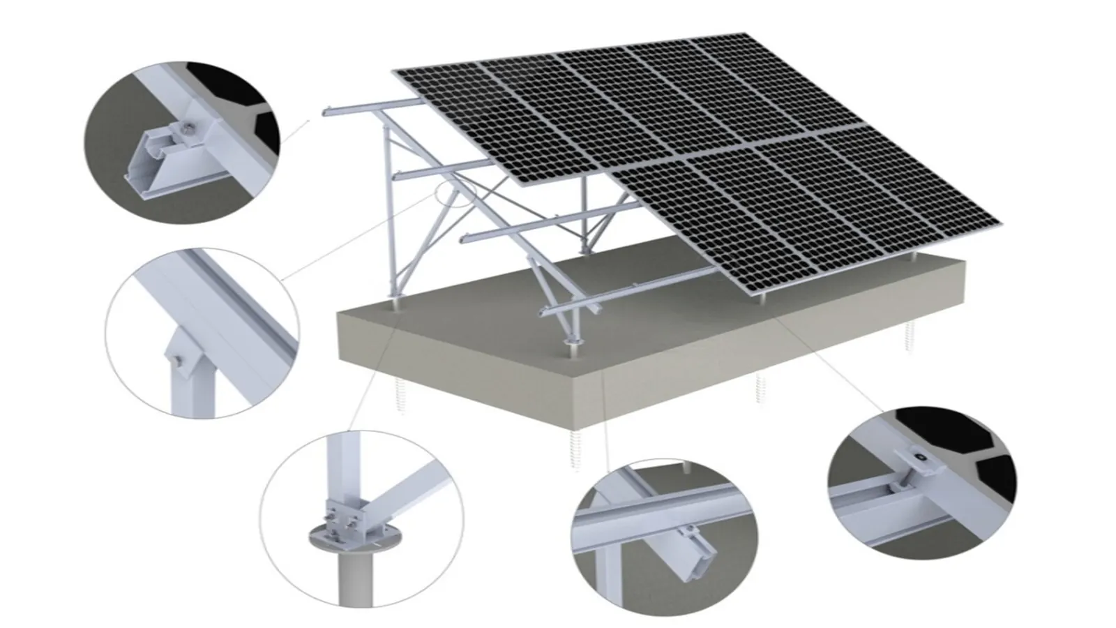
Detailed component sizes and quantities should follow the final approved structural configuration and BOM rather than a generic component list.
Materials & Corrosion
| Material | Typical Ground-Mount Role | Key Review |
| Galvanized / coated steel | Ground screws, piles, posts, beams, braces, base plates | Structural demand, coating, soil/atmospheric corrosion |
| Aluminum | Rails, clamps and selected upper-structure components | Weight, section design, corrosion environment |
| Stainless steel | Fasteners, grounding hardware and selected connection parts | Grade, joint design and compatibility with adjacent metals |
Material selection should consider the actual site. Marine exposure, industrial pollution, agricultural agents, moisture and aggressive soil can increase corrosion risk. DOE corrosion guidance also highlights galvanic corrosion where dissimilar metals are in electrical contact in the presence of moisture or another electrolyte.
For this reason, corrosion review should cover the complete assembly—including foundations, structural members, fasteners, bonding components and interfaces between different metals.
Ground Mount Installation Workflow
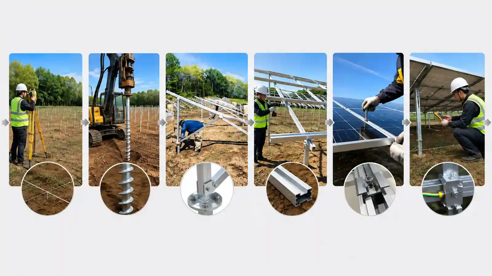
1. Confirm the Approved Layout and Survey
Verify site boundaries, row coordinates, table dimensions, module orientation, tilt, foundation grid and access routes. Installation should follow the confirmed drawing revision.
2. Set Out the Foundation Grid
Survey and mark foundation locations. Errors at this stage can propagate into post, beam, rail and module alignment problems later.
3. Install and Verify Foundations
Install the approved piles, ground screws, concrete foundations or other foundations. Check position, elevation, verticality/angle, embedment or installation criteria and connection condition. Perform field verification where required by the project.
4. Install Posts, Beams and Bracing
Connect the primary frame to the foundation, install bracing and secondary members, and verify geometry before module installation. Selected bracket/post/beam assemblies may be pre-assembled before shipment where the system and logistics allow it.
5. Align Module Supports and Install Modules
Confirm rail or purlin spacing against the final module datasheet. Install modules at the approved clamp zones and use the required fastener/torque procedure.
6. Complete Grounding, Cable Support and Final Inspection
Complete bonding, grounding and cable support according to the electrical design. Final structural inspection should verify foundations, alignment, bracing, fasteners, clamps, grounding parts, clearance, drainage and access. Record the completed configuration for handover.
Issues Easy Solar Checks in Ground-Mount Project Reviews
Before a ground-mount configuration is finalized, Easy Solar reviews the project inputs for issues that can change the foundation, structural geometry, component quantities or final BOM. The following checks are especially important during project review:
- Choosing the foundation before reviewing soil and site conditions.
- Finalizing the table layout before confirming the final PV module datasheet.
- Using the same row spacing or GCR for every site.
- Ignoring drainage, erosion, vegetation or access-road effects.
- Ignoring frost, groundwater or corrosion conditions around foundations.
- Underestimating wind demand on high-clearance or exposed structures.
- Treating bolts, clamps and other fastened joints as commodity parts rather than structural connections.
- Using an old BOM after the module, table, foundation or drawing revision has changed.
- Assuming CAD adjustability can absorb unlimited foundation and installation tolerance.
Information Easy Solar Reviews Before Preparing a Ground-Mount Configuration
The following information is used to organize a preliminary engineering review, product configuration and quotation. A customer does not need every item at the first contact, but missing site or load information can limit how far the structural configuration can be confirmed.
| Project Information | Why It Matters |
| Project country and location | Wind, snow, corrosion and design basis |
| Site plan / available land | Array arrangement and access |
| Topographic survey | Terrain and elevation strategy |
| Soil / geotechnical information | Foundation selection and verification |
| Groundwater / frost information | Foundation durability and depth considerations |
| PV module datasheet | Module dimensions, weight, frame and clamp zones |
| Module quantity and orientation | Table geometry and component quantities |
| Desired tilt / energy layout | Frame geometry and row spacing |
| Wind and snow requirements | Structural and foundation design inputs |
| Ground clearance | Post height, snow shedding and access |
| Foundation preference, if any | Starting point for engineering review—not final confirmation |
| Corrosion environment | Material/coating review |
| Site photos / drawings | Construction and terrain understanding |
| Required delivery scope | BOM, packing and quotation scope |
Incomplete information does not prevent an initial discussion, but the final structural configuration should not be treated as confirmed until the required engineering inputs are reviewed.
Common Questions About Ground Mount Solar Racking
What is a ground mount solar racking system?
It is a freestanding structural system that supports PV modules on open land and transfers module loads through the frame and foundation into the ground. It can include foundations, posts, beams, braces, purlins or rails, clamps, fasteners, grounding and cable-support components.
What is the difference between fixed-tilt and tracking ground mount?
Fixed-tilt racking holds modules at a designed angle. A tracker moves module rows during operation and adds moving components, control systems and different structural/foundation considerations.
What foundation is best for ground-mounted solar?
There is no universal best foundation. Driven piles, ground screws, concrete and selected ballasted concepts can all be appropriate depending on soil, structural reactions, frost, groundwater, corrosion, construction equipment and project restrictions.
How is pile or ground-screw depth determined?
Embedment is project-specific. It depends on soil conditions, foundation geometry, compression/uplift/lateral reactions, frost, groundwater, corrosion and the applicable engineering verification.
Can ground mount solar be installed on sloped terrain?
Yes, but slope changes the structural and construction strategy. Depending on the system, the project may use terrain-following rows, stepped elevations, variable post lengths, selective grading or another site-specific approach.
What information is needed for a ground-mount proposal?
Provide the project location, module datasheet, module quantity/layout, site plan, terrain/topography, soil information, wind and snow requirements, desired tilt, ground clearance, foundation preference where applicable, corrosion environment and available photos or drawings.
Final Takeaway
Ground mount solar racking should be treated as a site-specific structural system—not as a collection of posts and rails. The soil helps determine the foundation. The module, table geometry and loads help determine the frame. Terrain, drainage and access influence the layout and installation strategy. Material and connection choices must match the environment.
For early project planning, define the site and soil conditions first, then review foundation options and structural configuration. Final foundation dimensions, table geometry and BOM should follow the approved project inputs and engineering verification.
For Easy Solar product options, review the Ground Solar Mounting Systems range. For a project-specific proposal, send your site information, module data, layout, soil conditions, wind/snow inputs and available drawings for engineering review.
Technical References
U.S. Department of Energy — Solar Photovoltaic System Design Basics
Used for fixed versus tracking PV system concepts and general PV structural design context.
View source
U.S. Department of Energy — Life Cycle of Photovoltaic Systems: Install and Commission a Photovoltaic System
Used for ground-mounted PV site, foundation, topography, soil, installation and commissioning considerations.
View source
U.S. Department of Energy — Severe Weather Resilience in Solar Photovoltaic System Design
Used for wind-resilient racking, bracing, fastened joints and structural load-path considerations.
View source
U.S. Department of Energy — Solar Photovoltaic Hardening for Resilience: Winter Weather
Used for snow, ice, frost and foundation considerations in cold climates.
View source
U.S. Department of Energy — Managing and Mitigating Solar PV Corrosion
Used for corrosive-site assessment, material pairing and galvanic-corrosion considerations.
View source
National Renewable Energy Laboratory — Photovoltaic Stormwater Management Research and Testing (PV-SMaRT)
Used for ground-mounted PV stormwater, soil compaction, ground cover and array-spacing considerations.
View source
American Society of Civil Engineers (ASCE) — Foundation Alternatives for Ground Mount Solar Panel Installations Used for full-scale uplift-testing context across multiple solar foundation types and soil conditions. View source
Japanese Standards Association — JIS C 8955:2017, Load Design Guide on Structures for Photovoltaic Array
Referenced in the historical Easy Solar ground-mounted engineering example.
View source

Sales Manager at Easy Solar Solar Mounting Systems. With over 1o years of experience in the solar industry, I specialize in providing reliable andcost-effective mounting solutions for distributors, installers, and EPC companies. Experienced in intemational sales and commited to building long-term partnerships worldwide.