
How to Mount Solar Panels on a Metal Roof
Solar panels can be mounted on metal roofs by matching the roof attachment to the roof profile and verifying the complete load path. Compatible standing seam roofs may use clamps without new penetrations, while trapezoidal and corrugated roofs commonly use mechanically fastened attachments with suitable sealing details. The mounting system must also match the modules, roof condition, structural supports, and project wind and snow requirements.
For installers, EPC contractors, and distributors, a useful selection starts with roof photos, a profile drawing, module information, and the project’s design requirements. These inputs determine which attachments, supports, clamps, and fasteners belong in the mounting configuration.
Metal Roof Solar Mounting at a Glance
Roof profile determines the attachment interface. The following table provides a starting point for selection; the final configuration needs verification against the actual roof and mounting system.
| Roof profile | Common attachment options | New penetrations | Main checks |
|---|---|---|---|
| Standing seam | Compatible seam clamps with rails, short supports, or direct attachment | Often avoidable with a suitable clamp system | Seam geometry, roof metal, tested connection capacity, roof fixings, and thermal movement |
| Trapezoidal | Profile brackets, mini rails, L feet, or hanger bolt assemblies | Common in many systems | Rib dimensions, sheet thickness, fastening substrate, sealing, and module support positions |
| Corrugated | Brackets shaped for the profile, hanger bolt assemblies, or selected compact systems | Common in many systems | Corrugation shape, contact surface, supporting structure, fastener engagement, and sealing |
| Other metal roof constructions | Attachments approved for the particular roof construction | Depends on the system | Roof manufacturer requirements, structural load path, and water management |
Roof slope is assessed separately. A low-slope roof may use standing seam, trapezoidal, or corrugated panels, so slope alone does not determine whether the mounting system needs roof penetrations.
Review the available Metal Roof Solar Mounting System configurations once the roof profile is identified.
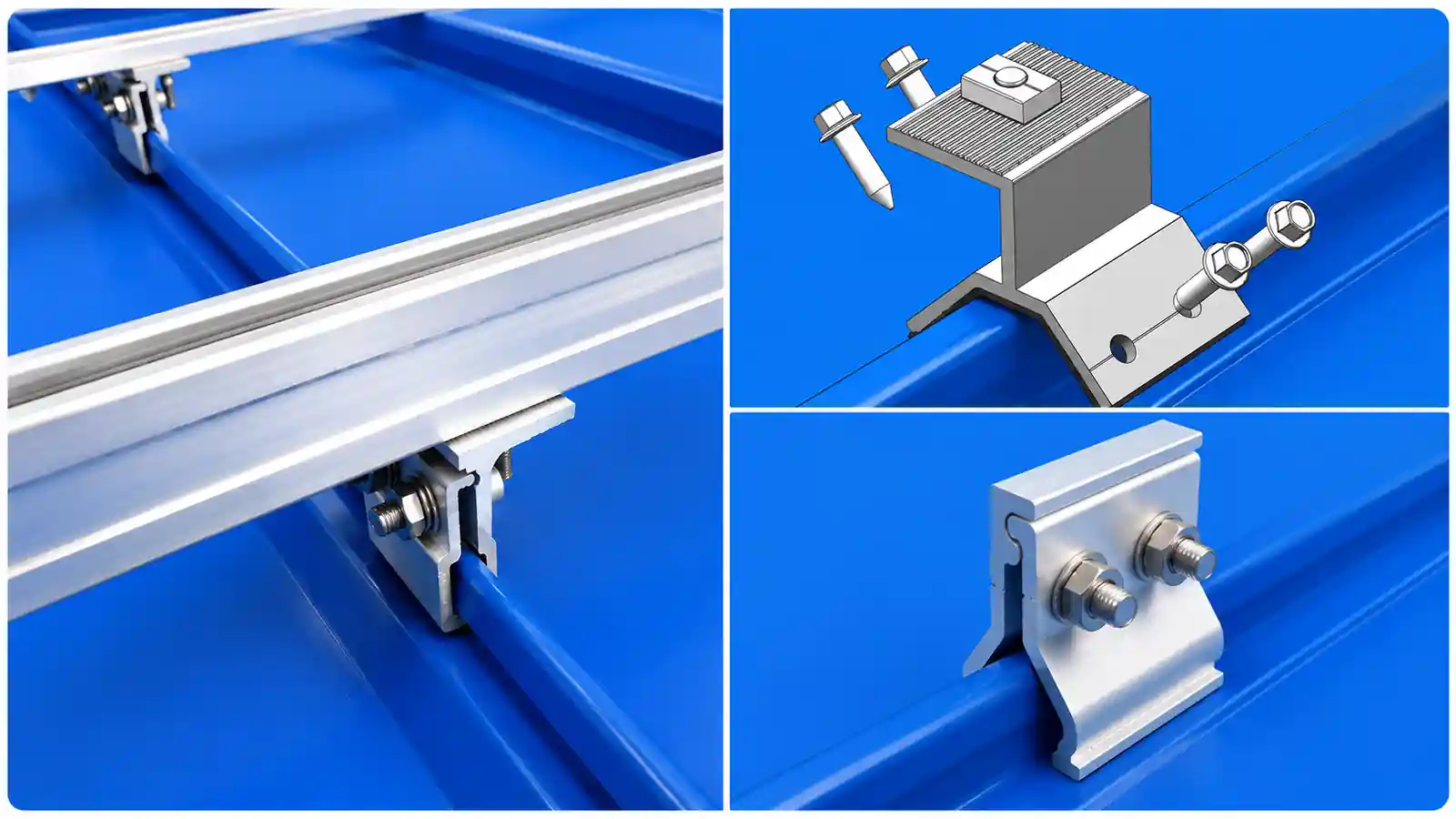
Identify the Roof Profile and Required Module Tilt
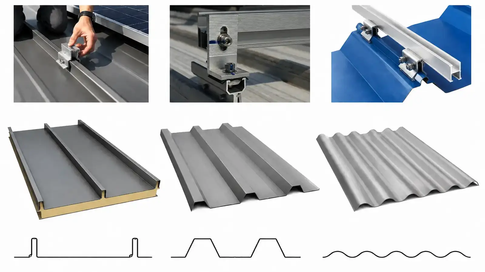
Standing Seam Metal Roofs
Standing seam roofs have raised seams and concealed roof fastenings. A compatible clamp can grip the seam and support the module mounting assembly without drilling a new hole through the roof panel at that connection.
Clamp selection requires the exact seam profile. Confirm seam shape and dimensions, panel material and thickness, the roof manufacturer’s system, and the tested clamp configuration. A clamp that appears to fit still needs verification for the required load direction and installation conditions.
Use clear roof photos and a cross-section drawing when reviewing standing seam solar mounting options.
Trapezoidal Metal Roofs
Trapezoidal panels have angular ribs separated by flatter areas. Crest width, rib height, rib spacing, and sheet thickness influence bracket fit and fastening options.
Some systems connect through the roof sheet into structural supports. Other engineered systems attach to the roof panel itself within defined material, thickness, and fastening limits. Verify which connection the selected system uses and how loads continue into the building.
For available configurations, see Trapezoidal Metal Roof Solar Mounting.
Corrugated Metal Roofs
Corrugated panels have a rounded, wave-shaped section. The curved surface affects how an attachment bears on the sheet and how its sealing components sit against the roof.
Use a bracket or fastening assembly intended for the actual corrugation. Check the specified fastening position, supporting member, and sealing detail. EcoFasten’s corrugated roof installation guidance illustrates product-specific attachments at rib tops or sides, away from drainage valleys; the correct position for another product must come from that product’s instructions.
Review Corrugated Metal Roof Solar Mounting for roof attachment options.
Low Roof Slopes and Additional Module Tilt
Roof slope is a separate design variable from roof profile. Modules can follow the roof plane, or an engineered frame can provide additional tilt where the project requires it. Tilted systems also need review of wind uplift, support reactions, row spacing, shading, roof access, and drainage.
A tilted frame still needs a suitable roof attachment. For example, K2’s CrossRail Simple Tilt System includes standing seam clamp options. The required module tilt does not automatically require a penetrative roof connection.
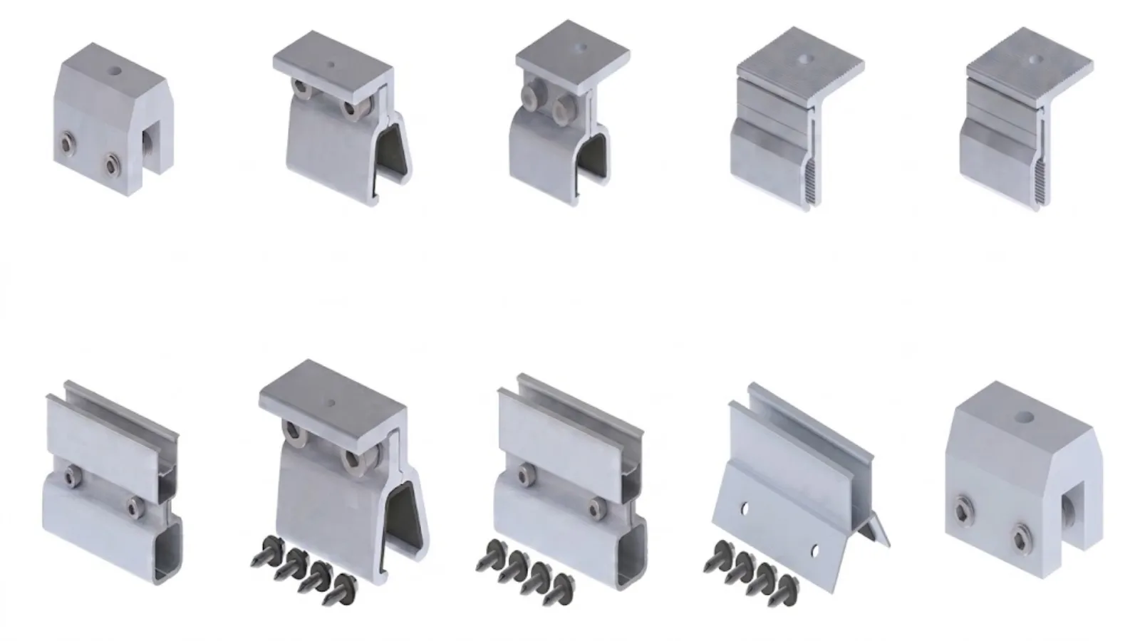
Choose the Roof Attachment and Module Support
Roof attachments connect the mounting assembly to the roof. Rails, short supports, and direct attachments provide the interface to the modules. Specify these parts together so their connections and capacities match.
Standing Seam Clamps
Seam clamps can support a rail interface or a system designed for direct module attachment. Selection should identify the clamp model, compatible seam, roof material, tested capacity, installation torque, and attachment layout.
Also review the roof panel’s connection to the building. On a roof that uses concealed clips, those clips and their fixings form part of the structural system supporting the PV array. S-5!’s standing seam attachment guidance explains why roof clips and seam strength can govern the design even when the clamp has adequate holding capacity.
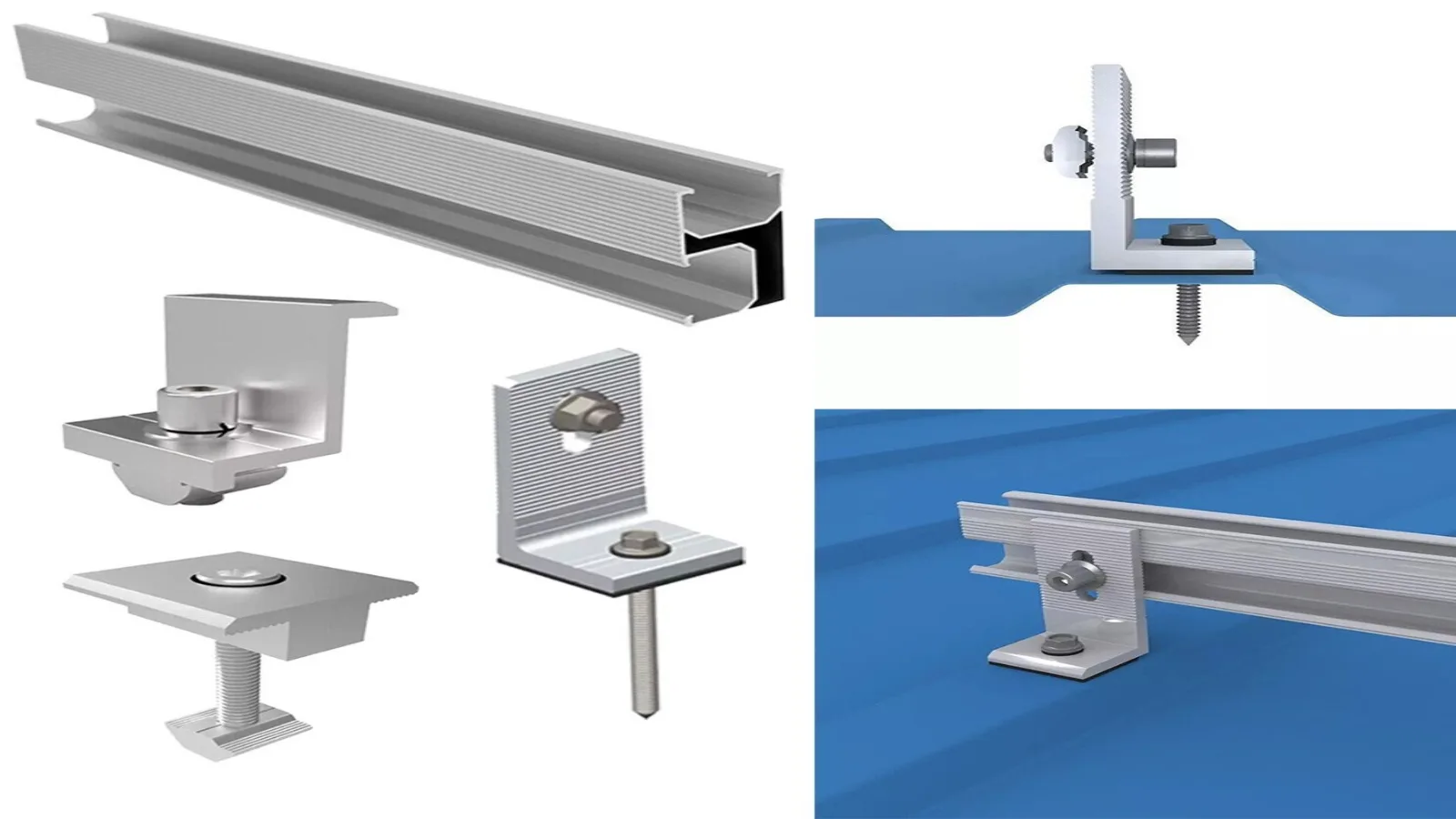
L Feet and Profile Brackets
An L foot provides an interface between the roof attachment and the rail, often with adjustment for rail position. The connection below it may use a profile bracket, a structural fastener, a hanger bolt, or a compatible seam clamp.
The L foot’s shape alone does not establish the roof connection. Specify the fastener, substrate, attachment geometry, and sealing detail as part of the assembly.
Hanger Bolt Assemblies
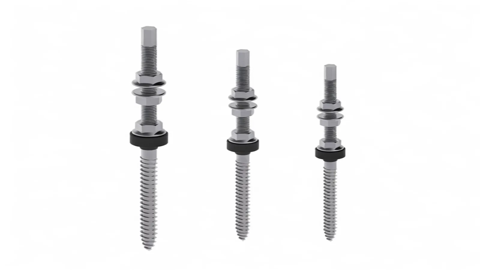
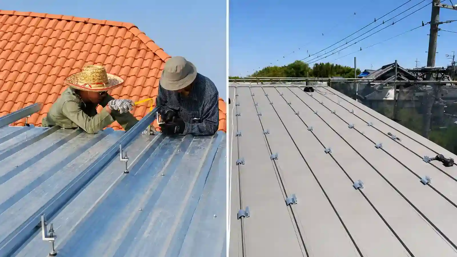
A hanger bolt assembly typically combines a fastener, sealing component, adapter or L foot, and rail connection. It is used on selected corrugated and trapezoidal roof systems where the fastening design suits the support below the roof sheet.
Confirm the fastener’s compatibility with timber, steel, or the other specified substrate. Required engagement, corrosion protection, sealing, and installation method depend on the chosen assembly.
Full Rails, Mini Rails, and Direct Attachment
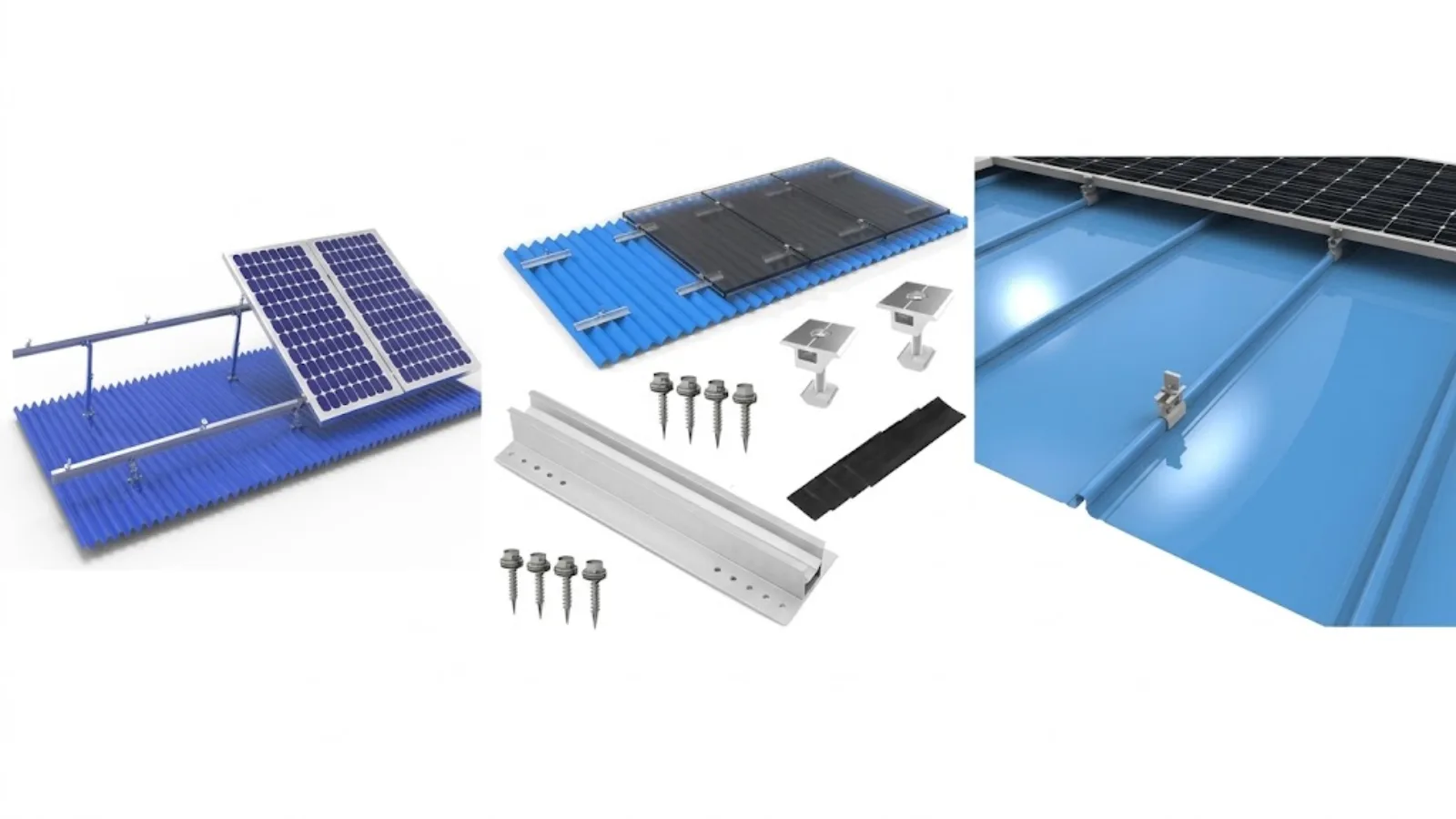
Mini rails are short rail sections. Direct attachment systems connect modules through dedicated roof-mounted interfaces and may eliminate separate mounting rails. Keep these categories distinct when comparing a bill of materials.
| Support system | How the modules are supported | Selection implications |
|---|---|---|
| Full rails | Modules clamp to longer rails spanning between roof attachments | Review rail spans, splices, overhangs, expansion provisions, and cable routing. Longer rails provide a continuous alignment interface. |
| Mini rails | Modules clamp to discrete short rail sections fixed at planned positions | Check each support location against module mounting zones, roof geometry, and connection capacity. Short sections reduce long-material handling. |
| Direct attachment | Dedicated interfaces connect modules to the roof attachment assembly | Use the complete approved system. Verify module compatibility, attachment locations, bonding provisions, and cable support. |
Compare complete installed configurations, including labor, freight, waterproofing parts, and accessories. Rail quantity alone does not determine project cost or suitability. For rail configurations, see Solar Panel Mounting Rails.
Verify the Roof and Project Design
Roof Condition and the Structural Load Path
Inspect the roof for corrosion, damaged seams, loose fixings, deformed panels, coating damage, and existing leakage. Consider the remaining roof service life and complete necessary repairs before covering the roof with an array.
Identify how the PV loads reach the building. Two typical arrangements are:
- Attachments to structural supports: PV module → module clamp → rail or other support → roof attachment → approved structural member → building structure.
- Attachments on a clipped standing seam roof: PV module → support or direct attachment → seam clamp → roof panel and seam → roof clips and their fixings → building structure.

An engineered connection directly to a roof sheet has its own load path through the panel and roof fixings. Its suitability must be established for that roof and mounting system. Existing roofing screws should be used as PV attachment points only where the mounting design expressly allows it.
For the wider relationship between mounting components and structure, read How Are Solar Panels Mounted.
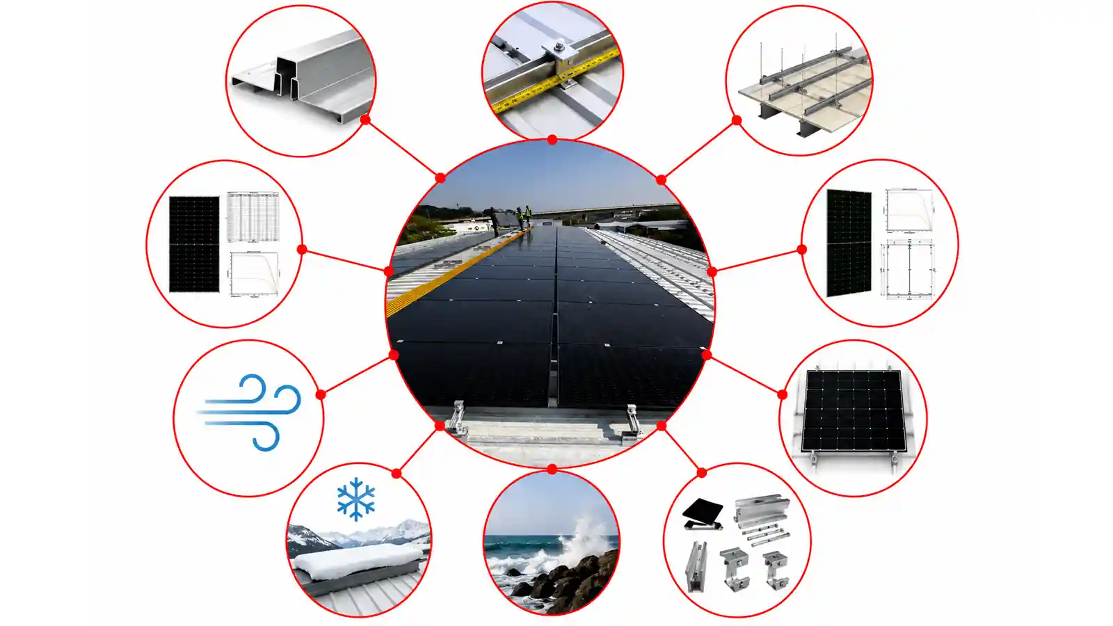
Module Layout and Wind and Snow Requirements
Confirm the module model, dimensions, weight, frame geometry, permitted mounting zones, orientation, and array layout. Use the module’s installation instructions as well as its datasheet when establishing support and clamp positions.
The structural design also needs the project location, applicable code and edition, building height and geometry, roof slope, exposure, array position, required module tilt, and wind and snow inputs. Attachment density and support arrangements may differ across roof zones.
A supplier’s generic wind-speed statement is insufficient to establish a project’s mounting layout. The design needs both the site demand and the capacities of the actual connections and supports. DOE’s severe-weather PV design guidance provides further context; see also How Wind Load Affects Solar Panel Mounting Systems.
Recheck the configuration when the module, tilt, attachment type, or layout changes. These revisions can affect rail spacing, clamp positions, roof reactions, and component quantities.
Thermal Movement and Roof Warranty
Coordinate mounting positions and rail expansion provisions with the roof’s movement requirements. Standing seam panels may accommodate thermal movement at the roof panel-to-clip interface or within the clips themselves. The mounting arrangement must preserve the movement required by that roof system.
S-5!’s technical note on thermal movement explains how clamp placement can depend on clip construction. Apply the instructions for the selected clamp and roof rather than adopting another roof’s fixing pattern.
Before installation, obtain the roof manufacturer’s requirements for solar attachments, penetrations, sealants, coating protection, and warranty conditions. Avoid assuming that a connection automatically preserves warranty coverage because it uses no new roof hole.
Materials and Corrosion Exposure
Specify materials and finishes for the roof metal and environment, including coastal or industrial exposure. Review fastener grades, coatings, sealing compounds, and any required isolation between materials with the mounting and roof manufacturers.
Remove metal drilling debris and protect damaged coatings as required by the roof instructions. Material selection and installation condition both affect the durability of the connection.
How to Mount Solar Panels on a Metal Roof
The following steps describe the mechanical mounting workflow. Use the drawings approved for the project, the mounting system’s installation instructions, and the module manufacturer’s mounting requirements. Electrical wiring and commissioning follow the project’s electrical design and applicable requirements.
Step 1: Confirm the Roof and Installation Documents
Check that the roof profile, supporting structure, module model, attachment layout, and bill of materials match the approved design. Confirm roof access and site installation arrangements before starting work.
Have the relevant product instructions available for attachments, rails, clamps, sealing components, and bonding hardware. These documents establish installation requirements for each connection.
Step 2: Mark Attachment and Support Positions
Lay out the array and mark the specified fastening or clamp positions. Check alignment, drainage routes, maintenance access, roof movement requirements, and module support zones before installing hardware.
For connections to structural supports, confirm the actual support locations. For a system designed to connect to the roof sheet, confirm the panel and fastening conditions required by that design.
Step 3: Install the Roof Attachments
Standing seam clamp installation
- Match each clamp to the confirmed seam and install it at the specified location.
- Check any restrictions associated with roof clips and thermal movement before tightening.
- Tighten the clamp fasteners to the installation requirements for that clamp and roof combination.
- Fit and inspect the specified rail adapter or direct attachment interface.
Installation of attachments with roof penetrations
- Confirm the fastening position, supporting substrate, and required fastener engagement.
- Prepare holes only as required by the chosen fastening system, and install the specified fasteners and sealing parts.
- Seat and tighten washers, pads, or other seals according to the product instructions, keeping the drainage path clear.
- Remove drilling debris, check coating damage, and inspect the completed attachment and seal.
Waterproofing must be designed into the connection. Additional sealant cannot establish an adequate structural connection or correct an attachment that sits incorrectly on the roof. PNNL’s roof anchor guidance discusses roof connections and sealing; metal-roof details still need to follow the applicable product and roof instructions.
Step 4: Install Rails or Other Module Supports
Align the supports before placing modules. Check rail span, splice position, overhang, support spacing, and required expansion provisions against the drawings and installation manual.
For mini rails and direct attachment, verify each support location carefully. The module must engage the intended interface within its permitted mounting zone. Plan the cable route at this stage so cable support is included in the assembly.
Step 5: Position and Clamp the Modules
Use module clamps compatible with the module frame and support system. Check the permitted clamp arrangement, engagement, position, and tightening requirements in the module and mounting instructions.
Mid clamps generally connect adjacent module frames; end clamps secure the outer edges of a row. Direct attachment systems may use dedicated interfaces instead. Maintain the specified gaps and clearances, and check alignment before final tightening.
Step 6: Complete Bonding and Cable Support
Install the bonding and grounding components specified for the mounting assembly and electrical design. Verify compatibility of clips, washers, lugs, and other interfaces using the system documentation.
Support PV cables with suitable clips, trays, or other specified accessories. Route them clear of sharp edges, standing water, drainage paths, and moving or abrasive contact points. Check cable clearance around module frames and roof attachments.
Step 7: Inspect the Installation and Record the Result
Inspect roof attachments, seals, rail connections, module clamps, alignment, bonding components, and cable support. Complete the required tightening and inspection checks, using the product’s stated procedure.
Record the installed configuration, relevant checks, any approved changes, and roof damage or repairs. Retain the installation documents for maintenance and future work. DOE’s PV installation and commissioning guidance describes the wider installation and handover process.
Common Metal Roof Mounting Mistakes
- Ordering clamps from a general roof photo without confirming the seam cross section.
- Selecting a roof bracket without establishing its fastener, substrate, and sealing arrangement.
- Treating mini rails as interchangeable with a direct attachment system.
- Reusing attachment spacing after changing modules, roof geometry, or tilt.
- Installing supports across movement provisions without the required design detail.
- Leaving drill swarf, damaged seals, unsupported cables, or coating damage at handover.
Project Reference for Tilted Mounting on a Metal Roof
Easy Solar’s Philippines 275.5 kW metal roof project reference documents a 15° triangle support arrangement. The published drawing shows a table of 23 modules, rail and module connections, and a roof-side support detail.
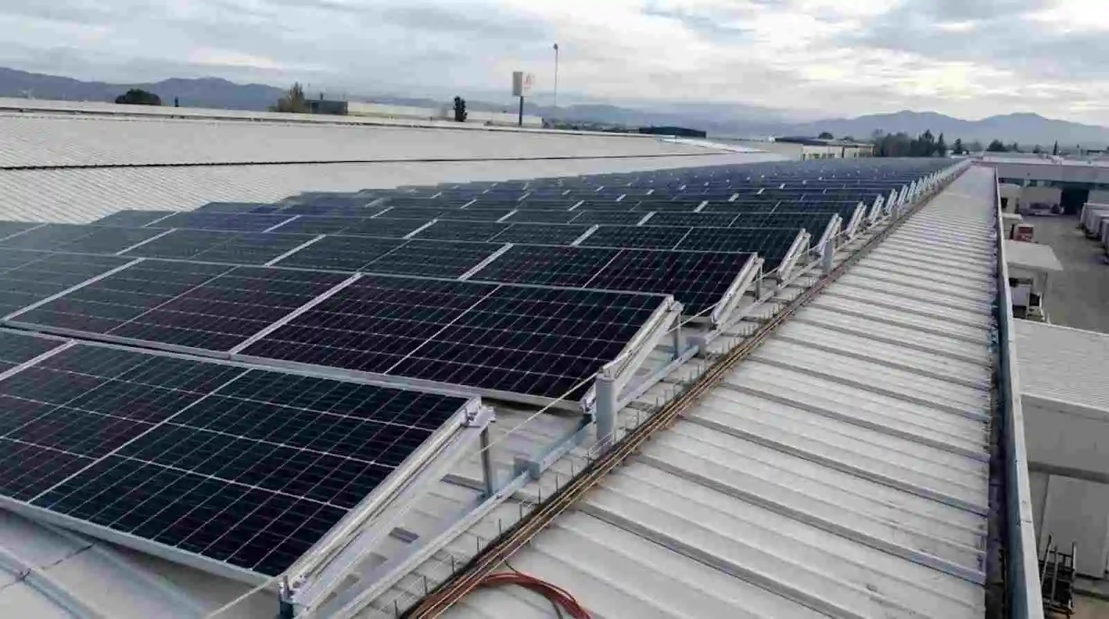
This example separates module tilt from the roof attachment decision. The triangle frame establishes the module angle, while the roof connection needs verification for the roof profile, supporting member, and sealing method. Its documented dimensions and load inputs belong to that project reference and must be reassessed for another roof.
What to Send for a Metal Roof Mounting Recommendation
A quotation request should describe the roof and array clearly enough to identify the attachment family and required design review. Include the following information where available.
| Information | Details to provide |
|---|---|
| Roof profile and geometry | Roof photos, cross-section drawing, seam or rib dimensions, roof slope, building height, and usable roof area |
| Roof material and condition | Roof manufacturer, panel metal and thickness, coating, condition, remaining service life, and relevant roof drawings |
| Supporting structure | Purlin, rafter, deck, or other support type and spacing; roof clip or fixing information where applicable |
| Modules and array | Module datasheet and mounting instructions, module quantity, orientation, row layout, and required tilt |
| Structural design inputs | Project location, applicable design basis, wind and snow requirements, exposure information, and available engineering documents |
| Restrictions and environment | Penetration limits, roof warranty requirements, thermal movement provisions, corrosion exposure, and access or drainage constraints |
| Procurement scope | Required component scope, drawings or bill of materials, estimated quantity, delivery destination, and packing requirements |
Describe the units and design basis of any wind or snow values supplied. A value without its definition can lead to the wrong design assumption. For help preparing the mounting inputs, review Engineering Support.
Common Questions About Metal Roof Solar Mounting
Can Solar Panels Be Installed Without Drilling?
Compatible standing seam roofs can often use seam clamps without new penetrations at the clamp locations. Corrugated and trapezoidal roofs commonly use mechanically fastened attachments, so the connection and sealing method need confirmation for the actual system.
Does Every Attachment Need to Connect to a Purlin?
Many attachments connect to purlins, rafters, or another structural member. Some engineered systems connect to the roof panel itself. The approved mounting design must establish the complete load path, including the panel and its roof fixings where relevant.
How Do You Choose a Standing Seam Clamp?
Identify the exact seam profile, roof material and thickness, and required mounting interface. Verify the tested connection, load direction, installation requirements, and any roof clip or thermal movement restrictions.
Are Mini Rails the Same as Rail-Less Mounting?
Mini rails use discrete short rail sections to support modules. A system with direct attachment may eliminate separate rails and uses its own module interface. Compare them as complete systems with different compatibility and layout requirements.
How Are Leaks Prevented Around Solar Attachments?
Where penetrations are required, use the sealing and water-management detail specified for the attachment and roof. Check contact surfaces, seal installation, drainage, and fastener tightening. Seam clamps that avoid new holes still need correct compatibility and installation.
Will Solar Mounting Affect the Roof Warranty?
Warranty conditions depend on the roof manufacturer and installation arrangement. Confirm permitted attachments, penetration details, sealants, coating protection, and movement requirements before work begins.
Can a Low-Slope Metal Roof Use Tilted Modules?
Yes, where an engineered mounting design and the roof structure can accommodate them. Select the roof attachment from the actual profile and review the additional tilt, wind reactions, row spacing, access, and drainage requirements.
What Changes? When the Module Model Changes?
Dimensions, frame geometry, mounting zones, weight, or allowable clamp arrangements may change. Review the supports, clamps, attachment positions, structural design, and bill of materials before using the revised module.
Select a Solar Roof Racking System for Your Metal Roof Project
Start with the roof profile and supporting structure, then select the attachment and module support configuration. Confirm the design inputs, sealing details, material compatibility, and installation documentation before ordering the complete component set.
Explore Metal Roof Solar Mounting Systems for available configurations.
Send Your Roof Profile for a Mounting Recommendation
Include roof photos, profile dimensions, module information, array layout, and the available wind and snow requirements with your request.
For a comparison across metal, tile, and flat roofs, see Solar Panel Roof Mounting Systems.
References and Technical Reading
- S-5! Solar Mounting on Metal Roofs
- S-5! Clamp Attachment and Roof Support Guidance
- S-5! Roof Panel Thermal Movement
- EcoFasten Installing Solar Panels on Corrugated Metal Roofing
- K2 CrossRail Simple Tilt System
- PNNL Roof Anchor System for Solar Panels
- DOE Severe Weather Resilience in Solar Photovoltaic System Design
- DOE Install and Commission a Photovoltaic System

Sales Manager at Easy Solar Solar Mounting Systems. With over 1o years of experience in the solar industry, I specialize in providing reliable andcost-effective mounting solutions for distributors, installers, and EPC companies. Experienced in intemational sales and commited to building long-term partnerships worldwide.