
Rail-Based vs Railless Solar Mounting Systems
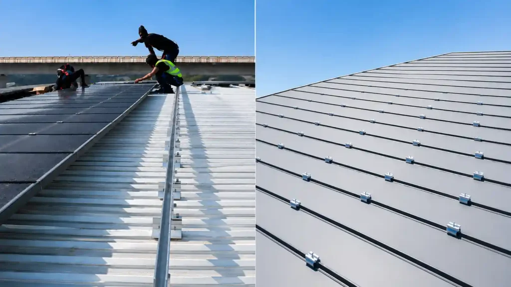
Rail-based and railless solar mounting systems solve the same basic problem in different ways: they connect PV modules to the roof or supporting structure while keeping the modules aligned, restrained, bonded, accessible, and structurally supported.
A rail-based system uses continuous rails as the main module-support and alignment interface. Roof attachments connect the rails to the building, and module clamps secure the panels to the rails.
A railless solar mounting system removes the continuous rail layer. Instead, the module is connected through short mounting devices, direct-attach brackets, seam clamps, module connectors, or other system-specific hardware.
The important point is that railless mounting does not eliminate the structural functions performed by a rail.
Those functions still have to exist somewhere else in the system.
This is why the best choice is not simply “more aluminum versus less aluminum.” The real comparison involves structural load transfer, field tolerance, installation labor, logistics, module compatibility, roof type, bonding, cable management, serviceability, and project-specific limitations.
PNNL describes conventional rooftop PV mounting as commonly using two rails with modules clamped to them, while also recognizing mounting systems that eliminate the rail layer.
For the broader physical mounting chain, read How Are Solar Panels Mounted?. For project-level selection, see How to Choose a Solar Mounting System for a PV Project.
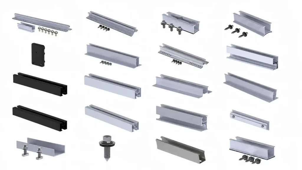
For rail products and profiles, see Solar Panel Mounting Rails.
Rail-Based vs Railless Solar Mounting at a Glance
| Factor | Rail-Based Mounting | Railless / Direct-Attach Mounting |
|---|---|---|
| Main Module Support | Continuous rail | Localized direct supports or module-to-module / module-to-roof interfaces |
| Alignment Reference | Rail provides a continuous reference line | Attachment points and module geometry provide the reference |
| Long Material Handling | More long extrusions | Reduced or eliminated |
| Rooftop Material Quantity | More rail material | Often less long-profile material |
| Installation Tolerance | Rails can absorb some attachment-position variation | Usually more dependent on accurate attachment placement |
| Module Compatibility | Rail + clamp compatibility | System-specific module/frame compatibility can be more critical |
| MLPE / Cable Support | Rail often provides a convenient support interface | Requires dedicated or integrated support strategy |
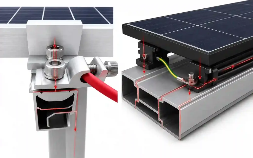
| Bonding / Grounding | Rail can form part of the bonding path in listed systems | Bonding must be verified across direct interfaces |
| Roof Applications | Broad roof compatibility with appropriate attachments | Most common on selected rooftop systems |
| Layout Flexibility | Strong adjustment and alignment flexibility | Can simplify some layouts but may impose system-specific geometry limits |
| Logistics | Long rails affect packing, transport, storage, and rooftop handling | Compact hardware can reduce long-material logistics |
| Best Fit | Projects valuing adjustability, familiar workflow, accessory integration and broad compatibility | Projects where direct attachment, compact logistics and reduced rail handling fit the roof and module |
Neither column is automatically better.
The correct decision depends on which architecture fits the roof, module, structural support, installer workflow, and required system approvals.
What Is a Rail-Based Solar Mounting System?
A traditional rail-based rooftop system generally follows this load path:
PV Module → Module Clamp → Aluminum Rail → Roof Attachment → Structural Member
The rail performs several jobs at the same time.
It can:
- Support multiple modules along a continuous line
- Provide a reference for module alignment
- Distribute module loads between attachment points
- Provide a channel for mid clamps and end clamps
- Connect to L feet, roof hooks, seam clamps, or other attachments
- Provide splice locations for long rows
- Support selected bonding and grounding components
- Provide attachment locations for cable clips or MLPE accessories
This concentration of functions is why rails remain common across many rooftop systems.
PNNL describes the typical rooftop arrangement as a rail system connected into roof structure, with panels then clamped to the rails. It also emphasizes module compatibility, structural support and proper roof integration rather than treating the rail as an isolated component.
Easy Solar’s current rail product architecture likewise treats the rail as the interface connecting module clamps, roof hooks, L feet, brackets, splice connectors and grounding components.
Rail-based mounting can also appear outside rooftops. Ground mounts and carports often use rails or structural purlins as the direct module-support interface.
What Is a Railless Solar Mounting System?
A rail less solar racking system removes the continuous aluminum rail used in a conventional rooftop architecture.
Instead, the structural support can be created by combinations of:
- Direct roof mounts
- Module attachment brackets
- Standing seam clamps
- Short structural supports
- Module-to-module connectors
- Roof-profile-specific direct attachments
- System-specific clamp assemblies
A simplified load path can look like:
PV Module → Direct Mount / Connector → Roof Attachment → Structural Support
or, on selected metal roofs:
PV Module → Direct Module Hardware → Seam Clamp / Profile Attachment → Roof System
The exact architecture varies widely.
This is why “railless” should be treated as a system architecture, not as a universal component type.
Some rail-less solar mounting systems still use short profiles, skirts, links, cross-connectors, or localized support pieces. The defining feature is the absence of a continuous long rail acting as the primary module-support line.
PNNL similarly notes that some PV mounting systems eliminate the rails and therefore remove those additional rail connections, rather than eliminating the need for a properly designed mounting system.
The Key Difference: Where Do the Rail Functions Go?
The most useful way to compare rail-based and railless systems is to track the functions normally performed by the rail.
When the rail is removed, those functions do not disappear.
They migrate.
| Function Normally Provided by a Rail | In a Rail-Based System | In a Railless System |
|---|---|---|
| Module support | Continuous extrusion | Local direct supports / module connectors |
| Alignment | Rail line | Mount layout + module geometry |
| Load transfer | Rail spans between attachments | Individual attachment geometry / direct support path |
| Clamp interface | Rail channel | System-specific module mount |
| Adjustment | Rail slot / bracket adjustment | Local adjustment in mounts or connectors |
| Bonding | Rail + listed bonding hardware | Direct module-to-module / module-to-mount bonding path |
| Cable support | Rail clips / rail channel accessories | Frame clips, dedicated supports, system-specific cable parts |
| MLPE support | Rail-mounted brackets are common | Dedicated module-frame or direct-mount support may be needed |
| Splicing | Rail splice | Usually not needed as a long-rail function |
| Shipping geometry | Long extrusion | Mostly compact hardware |
This concept is the central engineering difference.
Railless mounting reduces one physical component layer, but it redistributes the responsibilities of that layer across other interfaces.
That is why component count alone is not enough to judge system simplicity.
1. Components: Fewer Rails Does Not Always Mean Fewer Decisions
Rail-based systems usually contain a recognizable component stack:
- Roof attachment
- L foot, hook, or clamp
- Rail
- Rail splice
- Mid clamp
- End clamp
- Fasteners
- Grounding / bonding parts
- Cable-management parts
Railless systems may remove rails and splices, but the design can rely more heavily on:
- Precise roof mounts
- Direct module brackets
- Module-to-module connectors
- Specialized bonding interfaces
- Dedicated wire-management hardware
- Roof-specific attachment geometry
From a procurement perspective, the better question is not:
“How many components are there?”
It is:
“How many critical interfaces must be selected, installed, inspected, and replaced correctly?”
DOE treats fastened joints throughout PV module mounting and racking as critical structural interfaces and notes that failures can result from inadequate strength, poor installation, vibration-induced loosening and clamp failure.
A rail-based system may have more physical material but a familiar interface hierarchy.
A railless system may have fewer bulky parts but more dependence on system-specific hardware and installation sequencing.
2. Labor: Compare Rooftop Work, Not Just Part Count
Railless mounting is often attractive because it reduces measuring, cutting, carrying, joining, and staging long rails.
That can reduce:
- Rail cutting
- Rail splice work
- Long-profile rooftop handling
- Scrap from cut rail lengths
- Warehouse storage for long extrusions
- Jobsite staging of rail bundles
However, the labor comparison is not universal.
Railless installation may require more precision when placing individual roof attachments because there is no long rail to absorb or visually hide small positional variation.
The actual labor result depends on:
- Roof straightness
- Rafter or purlin location
- Roof profile
- Layout complexity
- Module orientation
- Installer training
- Adjustment range
- Attachment spacing
- Access conditions
- Number of roof obstructions
- System-specific assembly sequence
A useful way to compare labor is to divide it into four categories:
- Layout labor
- Attachment labor
- Module-support / alignment labor
- Finishing labor for bonding, cable management, MLPE, skirts, and inspection
A system can save time in one category and add time in another.
3. Field Tolerance: Rails Act as a Structural Alignment Tool
This is one of the most important differences and one of the least discussed in simplified comparisons.
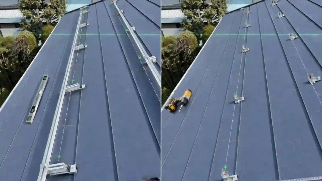
A continuous rail can act as a tolerance bridge.
If roof attachments are not perfectly collinear, adjustable L feet, slots, and the rail itself can help create a straight module-support line.
The rail therefore provides:
- A continuous installation datum
- Some lateral or vertical adjustment
- Easier row alignment
- A common support plane across multiple attachments
A railless system usually has less continuous correction available.
That does not make it inferior, but it changes the installation discipline.
The attachment coordinates, roof profile, module dimensions, and local adjustment features become more important.
For a B2B project, ask:
- How much adjustment is available at each mount?
- What roof irregularity can the system accommodate?
- How is module-row alignment established?
- How are attachment-position errors corrected?
- What happens when the roof surface is not perfectly flat?
- Can one module be replaced without disturbing adjacent modules?
This tolerance budget can be more important than the nominal number of parts.
4. Logistics: Long Rails Change the Supply Chain
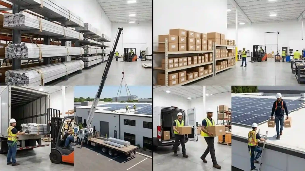
For manufacturers, distributors, EPC contractors, and installers, rail length creates a logistics problem that small hardware does not.
Long rails affect:
- Extrusion length
- Cutting plans
- Bundling
- Pallet design
- Container utilization
- Truck length
- Roadway width
- Warehouse racking
- Handling damage
- Rooftop lifting
- Jobsite storage
Easy Solar’s current rail product page itself treats rail length, cutting plan, transport-length splices, bundled export packaging and project-based packing as important parts of rail selection and supply.
Railless hardware can often be packed in smaller cartons or kits.
This can simplify:
- Warehouse storage
- Last-mile transport
- Rooftop lifting
- Project kitting
- Small-order distribution
- Spare-parts storage
But logistics should be compared at system level.
A compact railless kit may still require more roof-specific SKUs, more individual attachment pieces, or tighter module compatibility.
A rail-based system may ship long extrusions but allow more standardized clamp and attachment combinations across projects.
For export projects, compare:
Material weight + package dimensions + SKU count + installation sequence + replacement parts
rather than freight weight alone.
5. Module Compatibility Can Be More Important in Railless Systems
In a rail-based system, the rail and module clamp create an intermediate interface between the roof and module.
This can provide some flexibility when changing module sizes, provided the clamp zone, rail spacing, and structural design remain compatible.
In a railless system, the module frame can become more directly involved in the mounting architecture.
Check:
- Module frame thickness
- Frame geometry
- Approved clamp zones
- Approved mounting holes
- Module orientation
- Direct-mount interface
- Required module-to-module spacing
- Whether the mounting system is listed or approved with the module configuration
- Whether large-format modules change support spacing or structural demand
PNNL recommends confirming compatibility between the selected module and racking system and following the applicable product documentation.
Do not assume that a rail less solar mounting system that works with one framed module will automatically work with another.
A module revision should trigger a compatibility review.
6. Roof Type Matters More Than the Rail Question
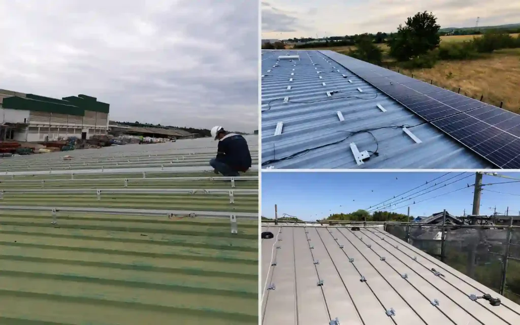
Rail-based versus railless is not the first rooftop decision.
The first decision is still the roof.
Tile and Shingle Roofs
Rail-based systems remain common because roof hooks, flashed anchors, or other attachments can connect to continuous rails that simplify alignment.
Railless systems also exist for selected sloped roofs, but the attachment and waterproofing architecture must be evaluated as a complete system.
PNNL emphasizes appropriate attachment to structural members and proper flashing and sealing when the mounting system creates roof penetrations.
Standing Seam Metal Roof
Standing seam roofs are especially suitable for evaluating direct-attach concepts because compatible seam clamps can provide repeated structural attachment lines without creating new penetrations through the roof panel.
A rail-based design can use:
Seam Clamp → Rail → Module Clamp
A direct-attach design can shorten that chain:
Seam Clamp / Direct Mount → Module
The exact seam geometry and system compatibility still need to be confirmed.
For metal-roof options, see Metal Roof Solar Mounting System. Easy Solar’s current metal-roof architecture covers standing seam, corrugated and trapezoidal applications.
Trapezoidal and Corrugated Metal Roofs
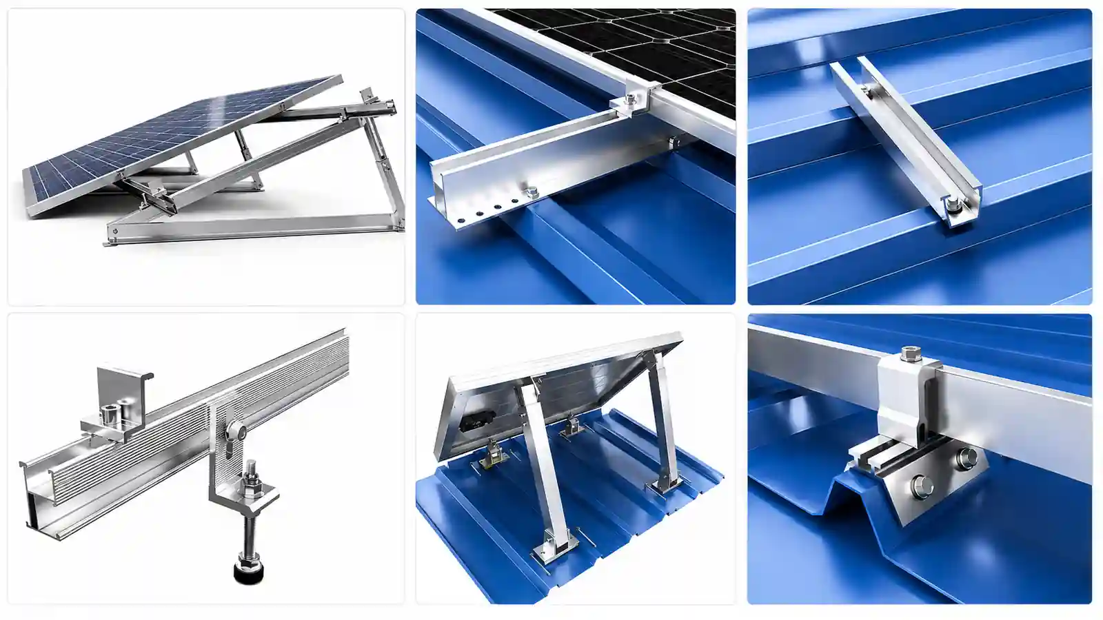
Selected profiled metal roofs can use:
- Long rails
- Short rails
- Mini rails
- Direct-attach brackets
Easy Solar’s current rail range likewise distinguishes conventional long rails and short metal-roof rail profiles for selected trapezoidal and corrugated applications.
The choice depends on rib geometry, structural support, sealing, attachment location, module support, and project loads.
This article keeps the metal-roof comparison at architecture level. A separate metal-roof article should handle the detailed decision between rail-based and railless configurations for standing seam, trapezoidal, and corrugated profiles.
Flat Roofs
On commercial flat roofs, “rail-based versus railless” is often not the main decision.
The larger structural question is usually:
- Ballasted
- Mechanically attached
- Hybrid
The module-support structure may use rails, trays, frames, or system-specific supports within those architectures.
This is why railless should not be used as a universal label for every system that does not look like a pitched-roof rail.
7. Wind and Snow: The Load Path Changes When the Rail Is Removed
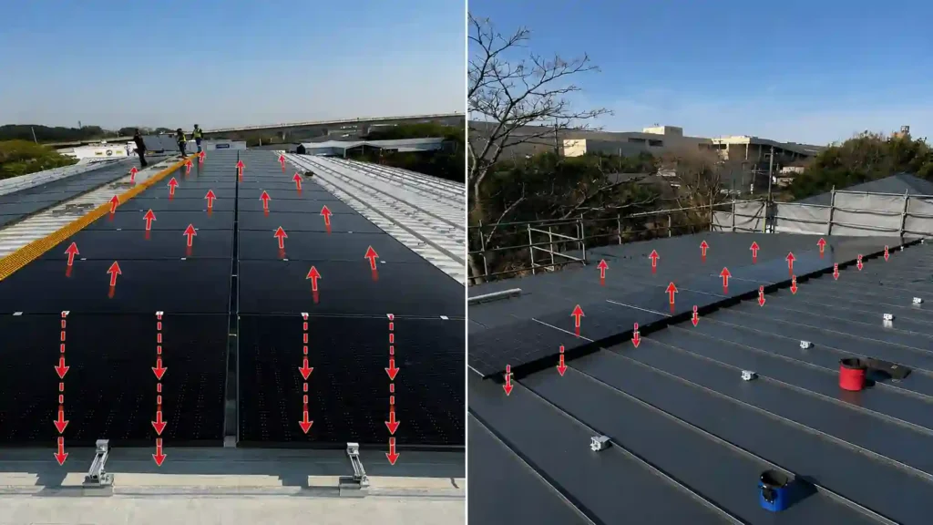
The mounting system has to transfer environmental loads regardless of architecture.
DOE identifies module mounting and racking fastened joints as critical structural connections and notes field failures involving inadequate strength, poor installation, vibration-induced loosening, and failed module mid-clamps.
In a rail-based system, the load path can be:
Module → Clamp → Rail → Attachment → Structure
The rail distributes reactions between support points according to the system design.
In a railless system, reactions can become more localized:
Module → Direct Mount → Attachment → Structure
This can make the following especially important:
- Module frame strength
- Direct-mount location
- Attachment spacing
- Fastener capacity
- Roof-member location
- Local uplift reactions
- Snow support configuration
- Module mounting zone
Do not assume that removing rail automatically reduces structural demand.
It changes how the demand is transferred.
DOE’s current installation guidance also emphasizes appropriately rated critical fastened joints and secure connections that are not vulnerable to torsional movement or racking flex.
For snowy regions, the module support arrangement should be checked against the module’s approved mounting configuration and the mounting system’s structural design.
8. Bonding and Grounding: The Rail May Be Part of the Electrical Path
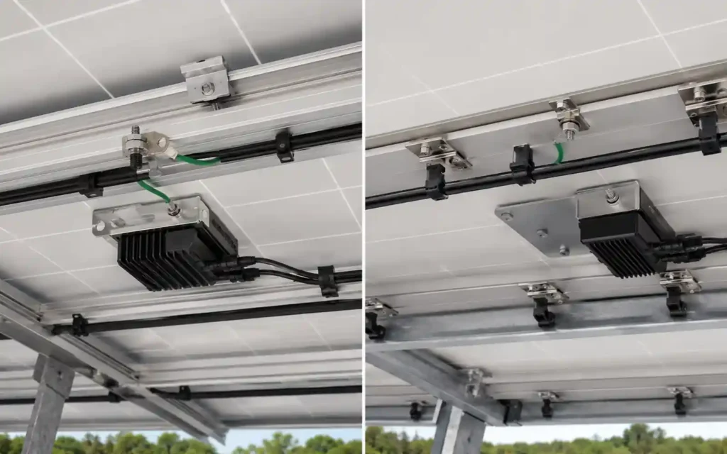
Mechanical simplicity does not remove electrical requirements.
UL 2703 covers mounting systems, mounting devices, clamping or retention devices, and ground lugs for use with flat-plate PV modules and panels. UL also notes that proper bonding and grounding are critical to PV electrical safety.
In a rail-based listed system, electrical bonding may use combinations of:
- Bonding mid clamps
- Bonding washers
- Rail splices
- Grounding lugs
- Bonding jumpers
- Grounding conductors
The rail can become part of the electrically continuous mounting assembly.
When the rail is removed, the bonding strategy must still connect the required exposed conductive parts.
A railless system may use:
- Module-to-module bonding
- Integrated bonding teeth
- Direct bonding mounts
- Dedicated jumpers
- Ground lugs
- System-specific listed hardware
The key question is not whether rails are present.
It is:
Is the complete module-and-mount assembly using a verified bonding and grounding method?
Do not improvise a grounding path based only on mechanical metal-to-metal contact.
9. Cable Management and MLPE Support Need an Explicit Plan
Rails often provide convenient mounting locations for:
- Cable clips
- Wire hangers
- Optimizer brackets
- Microinverter brackets
- Grounding conductors
- Cable-routing accessories
A railless system removes that continuous support line.
Cable management therefore needs to be intentionally designed around:
- Module-frame clips
- Dedicated wire supports
- MLPE mounting brackets
- Short cable spans
- Roof clearance
- Sharp edges
- Service loops
- Drainage
- Future module removal
DOE’s current DC-string cable-management guidance recommends supporting and routing PV wiring to prevent abrasion, sagging and long-term damage, and warns that inadequate cable supports can create electrical faults and maintenance problems.
This is an area where “fewer racking components” can create a new accessory requirement.
Compare the complete installed system, not just the structural hardware.
10. Maintenance and Module Replacement
A mounting architecture should also be judged by what happens after commissioning.
Ask:
- Can one module be removed without loosening a large section of the row?
- Can clamps or direct mounts be accessed after installation?
- Can cable clips be inspected?
- Can MLPE be replaced?
- Are spare proprietary connectors available?
- Can damaged rail sections be replaced?
- Can a direct-mount component be swapped without disturbing waterproofing?
- Can the installer identify the correct replacement SKU years later?
Rail-based systems can benefit from standardized interfaces and continuous access along the rail.
Railless systems can reduce long structural components but may rely more heavily on proprietary local interfaces.
Neither is automatically easier to maintain.
The service strategy depends on the specific system.
11. Rail-Based vs Railless: Which Is Better for Different Projects?
Rail-Based Mounting Is Often a Strong Candidate When:
- The roof has irregular geometry
- Attachment locations need adjustment
- Installers prefer a familiar workflow
- Multiple roof attachment types may be used
- Module-row alignment is a major concern
- MLPE and cable support need flexible attachment locations
- Tilt or additional structural adjustment is required
- The project needs a standardized rail-and-clamp architecture
- Long-rail logistics are manageable
Railless Mounting Is Often a Strong Candidate When:
- The roof and module are compatible with a direct-attach architecture
- Reducing long-rail handling is valuable
- Packaging and rooftop logistics are important
- Attachment positions can be laid out accurately
- The installation team is trained on the specific system
- The bonding and cable-management strategy is fully defined
- The roof profile offers suitable repeated attachment geometry
- The project benefits from compact hardware kits
Short-Rail / Mini-Rail Can Be a Middle Option
Not every project has to choose between a full-length rail and no rail at all.
Short-rail or mini-rail systems can retain a localized rail channel for clamps while reducing:
- Long extrusion handling
- Rail splices
- Cutting
- Shipping length
This can be especially relevant on selected metal roofs.
It is often more useful to think of mounting architectures as a continuum:
Full Rail → Shared Rail / Reduced Rail → Mini Rail → Direct Attach / Railless
rather than two completely separate categories.
A Five-Gate Decision Framework
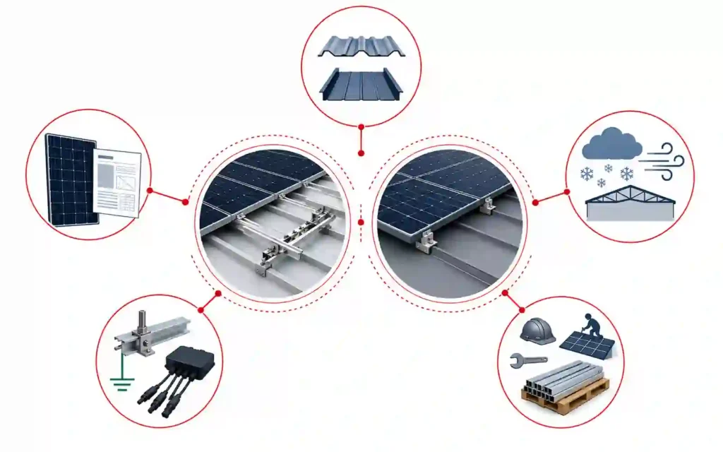
Before choosing a railless system over a rail-based system, pass five decision gates.
Gate 1: Roof Compatibility
Confirm roof material, structural support, waterproofing method, attachment geometry, and allowed penetrations.
Gate 2: Module Compatibility
Confirm frame dimensions, mounting zones, direct attachment interface, and orientation.
Gate 3: Structural Load Path
Confirm how wind, snow, dead load, and other reactions move from the module into the roof structure.
Gate 4: Bonding, Cable and MLPE Integration
Confirm grounding/bonding, cable support, optimizer or microinverter mounting, and inspection access.
UL’s mounting-system framework reinforces that mounting, clamping and grounding need to be considered as an integrated system rather than unrelated components.
Gate 5: Installation and Lifecycle
Compare labor, rooftop handling, installer training, adjustment range, spare parts, module replacement, logistics, and long-term service.
If a railless system passes all five gates and improves the project workflow, it can be a strong option.
If it fails one of the must-pass gates, the reduced rail material is not a sufficient reason to select it.
Common Mistakes When Comparing Rail and Railless Systems
Assuming Railless Always Means Faster
Installation speed depends on the roof, layout, installer experience, adjustment range, and finishing work.
Comparing Only Aluminum Weight
Freight and rooftop handling matter, but structural compatibility and system integration matter more.
Ignoring Roof Irregularity
A roof that is not flat or straight can expose the alignment limitations of a direct-attach system.
Assuming Fewer Parts Means Fewer Critical Connections
Critical structural and electrical interfaces still exist even when the rail is removed. DOE’s severe-weather guidance specifically identifies bolts, clips, brackets and module-to-racking joints as critical PV connections.
Ignoring Module Changes
Railless architectures can be highly dependent on module geometry.
Leaving Cable Management Until the End
Removing rails also removes a convenient continuous accessory-support surface.
Treating All Metal Roofs as the Same
Standing seam, trapezoidal, and corrugated roofs use different attachment logic.
Using Unverified Bonding Methods
Mechanical contact alone should not be assumed to provide the required bonding path.
What Information Should You Provide for a Rail vs Railless Review?
| Project Information | Why It Matters |
|---|---|
| Roof type and material | Determines attachment architecture |
| Roof profile dimensions/Roof cross-section drawings | Critical for metal-roof direct attachment |
| Structural member spacing | Defines attachment locations |
| Roof condition / warranty | Affects attachment and waterproofing |
| Module datasheet | Frame, dimensions, mounting zones |
| Module orientation | Affects support geometry |
| Array layout | Determines rail length or direct-mount coordinates |
| Wind / snow requirements | Defines structural reactions |
| Corrosion environment | Influences materials and fasteners |
| MLPE / inverter architecture | Affects accessory mounting |
| Cable-management requirements | Important when rails are removed |
| Installation labor model | Helps compare field time |
| Packing / shipping limits | Important for long rails |
| Maintenance expectations | Affects serviceability and spare parts |
For a rail-based quotation, you can also send the required rail profile, module data, support spacing, clamp interface, cutting length, and quantity through the Solar Panel Mounting Rails page. Easy Solar’s current rail page specifically requests rail profile, module data, support connection, length, clamp interface, quantity and packing information for project matching.
Common Questions About Rail Less Solar Mounting
What is rail less solar racking?
Rail less solar racking is a PV mounting architecture that secures modules without using continuous long mounting rails as the primary module-support line. Direct mounts, module connectors, seam clamps, short supports, or other system-specific components perform the required structural functions.
Is railless solar mounting better than rails?
Not universally.
Railless systems can reduce long-material handling and may simplify logistics, while rail-based systems provide continuous alignment, adjustment, and accessory support.
The better system depends on the roof, module, loads, installer workflow, bonding, cable management, and service requirements.
Does railless mounting use fewer roof penetrations?
Not necessarily.
Penetration count depends on the roof type, attachment spacing, structural design, and mounting system. A compatible standing seam direct-attach system may avoid new roof penetrations, while other railless systems can still use mechanically fastened roof attachments. PNNL notes that penetration and flashing requirements depend on the roof and attachment architecture rather than simply whether rails are present.
Are rail-less solar mounting systems only for metal roofs?
No.
Railless systems exist for several rooftop types, but metal roofs—especially compatible standing seam profiles—can be particularly suitable for direct-attach architectures.
Are rails stronger than railless mounting?
The presence of a rail alone does not determine structural capacity.
Strength depends on the complete load path, module support, attachment spacing, fasteners, roof structure, project loads, and tested or engineered system configuration. DOE’s guidance likewise focuses on the strength and reliability of the complete racking and critical-joint system rather than the presence of any one component.
Can railless systems support large-format solar modules?
Potentially, but module compatibility must be verified.
Large modules can change mounting zones, local reactions, support spacing, and frame demand.
Is rail-less solar mounting easier to ship?
Yes, rail-less solar mounting systems are generally easier and cheaper to ship. They use fewer and shorter components, which reduces package size, weight, and freight costs. Their compact design also makes handling, storage, and transportation more convenient.
How is grounding handled without rails?
Railless systems need a verified bonding and grounding path through system-specific module mounts, bonding hardware, jumpers, lugs, or other listed components.
How are cables supported in a railless system?
Cable support can use module-frame clips, dedicated cable hangers, MLPE brackets, or other system-specific accessories.
The cable plan should be designed before module installation, with wiring supported to prevent abrasion, sagging and damage.
When should I choose a rail-based mounting system?
Rail-based mounting is a strong candidate when the project values alignment flexibility, broad attachment compatibility, accessory mounting, familiar installation methods, and tolerance for roof variation.
Choose the Architecture, Not Just the Hardware
Rail-based and railless solar mounting systems should be compared as complete architectures.
A rail-based system concentrates several structural and installation functions into one continuous extrusion.
A railless system removes that extrusion and transfers its functions into the module mounts, roof attachments, module frame, bonding hardware, cable supports, and installation layout.
That can create real advantages in material handling and logistics.
It can also make compatibility, precision, bonding, cable support, and system-specific installation more important.
The correct choice should therefore follow this sequence:
Roof → Module → Load Path → Attachment → Alignment / Tolerance → Bonding → Cable / MLPE → Installation → Logistics → Maintenance
If the project benefits from continuous rails, explore Solar Panel Mounting Rails.
For broader rooftop options, see Roof Solar Mounting Systems. The current Roof Hub links both the rail and clamp component families and the major roof-type mounting categories.
For a project-specific comparison, send your project details with the roof profile, module datasheet, layout, structural spacing, wind and snow requirements, cable-management needs, and installation constraints. The current contact page is publicly accessible.
References & Technical Sources
- Pacific Northwest National Laboratory / Building America Solution Center — Roof Anchor System for Solar Panels
https://basc.pnnl.gov/resource-guides/roof-anchor-system-solar-panels - U.S. Department of Energy — Severe Weather Resilience in Solar Photovoltaic System Design
https://www.energy.gov/cmei/femp/severe-weather-resilience-solar-photovoltaic-system-design - UL Solutions — PV Mounting Systems Certification / UL 2703
https://www.ul.com/services/pv-mounting-systems-certification - U.S. Department of Energy — Solar Photovoltaic Cable Management: Best Practices for DC-String Cables
https://www.energy.gov/cmei/femp/solar-photovoltaic-cable-management-best-practices-dc-string-cables - U.S. Department of Energy — Life Cycle of Photovoltaic Systems: Install and Commission a Photovoltaic System
https://www.energy.gov/cmei/femp/life-cycle-photovoltaic-systems-install-and-commission-photovoltaic-system

Sales Manager at Easy Solar Solar Mounting Systems. With over 1o years of experience in the solar industry, I specialize in providing reliable andcost-effective mounting solutions for distributors, installers, and EPC companies. Experienced in intemational sales and commited to building long-term partnerships worldwide.