
How Are Solar Panels Mounted? Components and Installation Basics
Solar panels are mounted by attaching the modules to a compatible support system and securing that system to a roof assembly, ground foundation, or another designed structure. Framed modules commonly use mid clamps, end clamps, or bolts through manufacturer-designated mounting holes; some systems use dedicated direct-attachment hardware. The support arrangement, attachment locations, and fastening method must match the module, mounting system, site conditions, and project design.
On a conventional pitched roof, roof attachments support rails and module clamps secure the panels to those rails. Compatible standing-seam roofs may use seam clamps without new penetrations through the roof panels. Ground-mounted arrays use frames and foundations to transfer loads into the soil.
For installers, EPC contractors, and distributors, the practical task is to coordinate these connections with the drawings, installation instructions, and bill of materials.
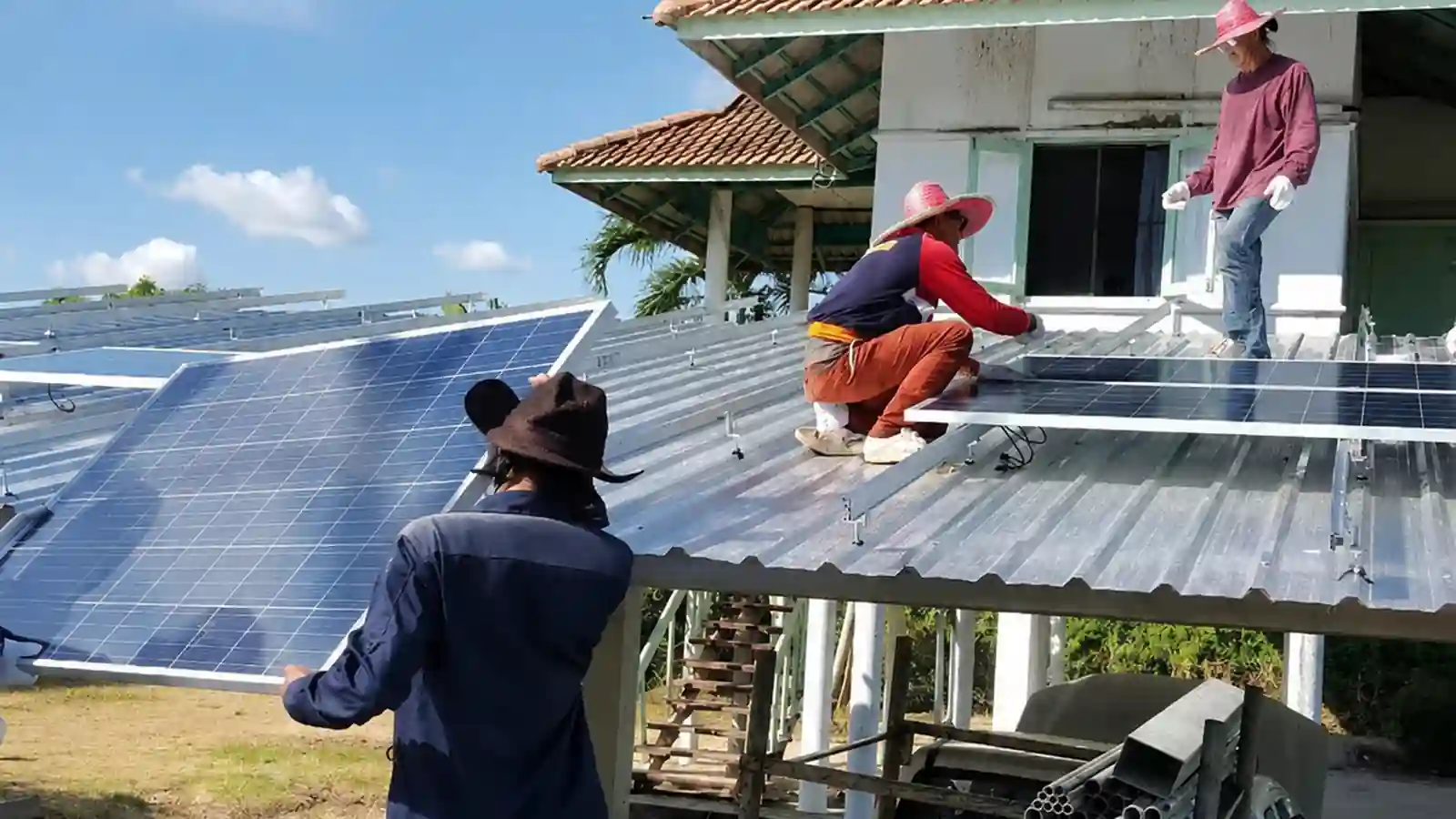
What Holds Solar Panels in Place?
A mounting assembly performs three main mechanical functions: retaining the modules, supporting the array, and connecting it to the building or ground.
Module Clamps and Mounting Bolts
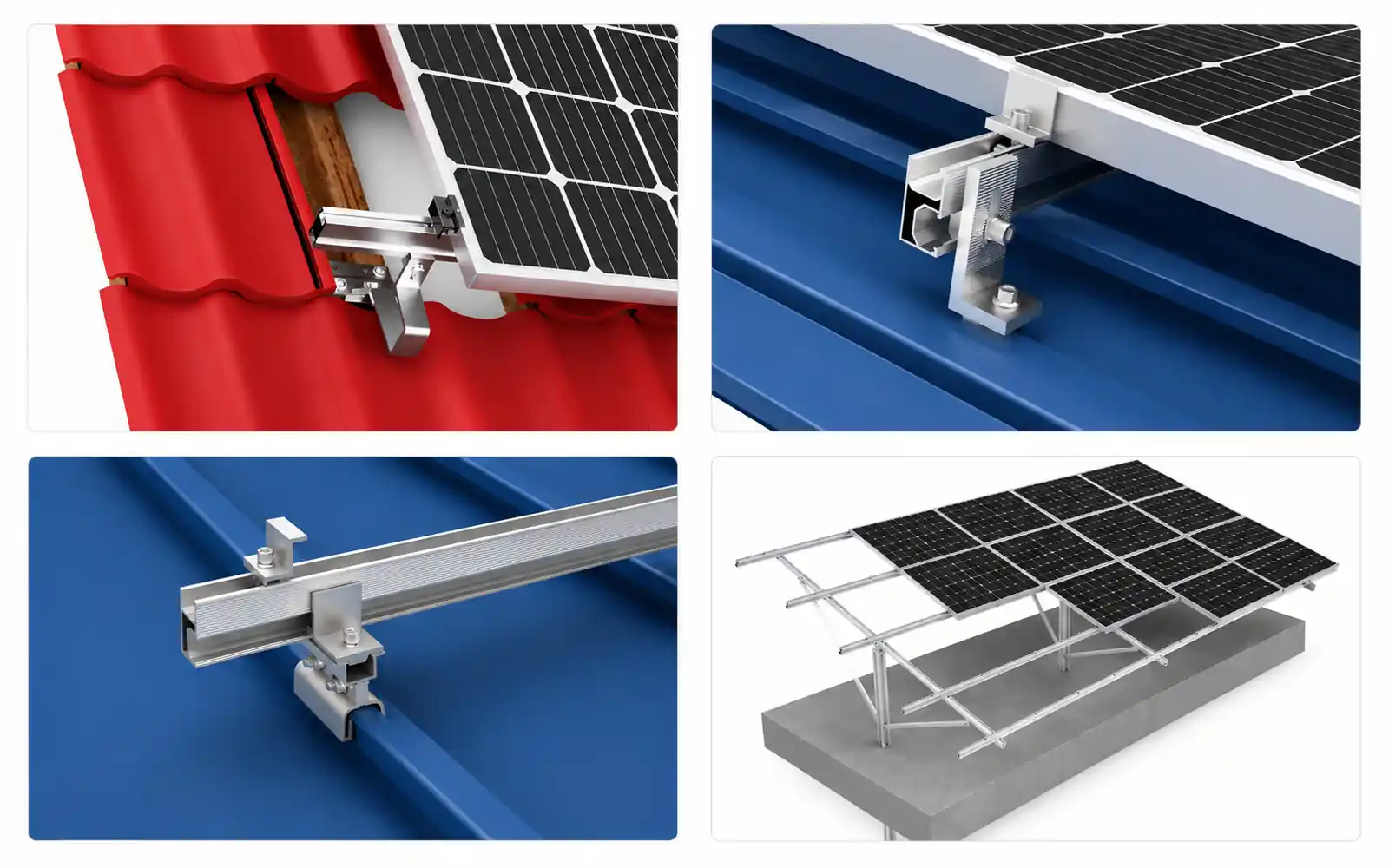
A mid clamp typically engages the frames of two adjacent modules. An end clamp retains a module at the outside of a supported row or group. Their fasteners engage the mounting rail or another dedicated support interface.
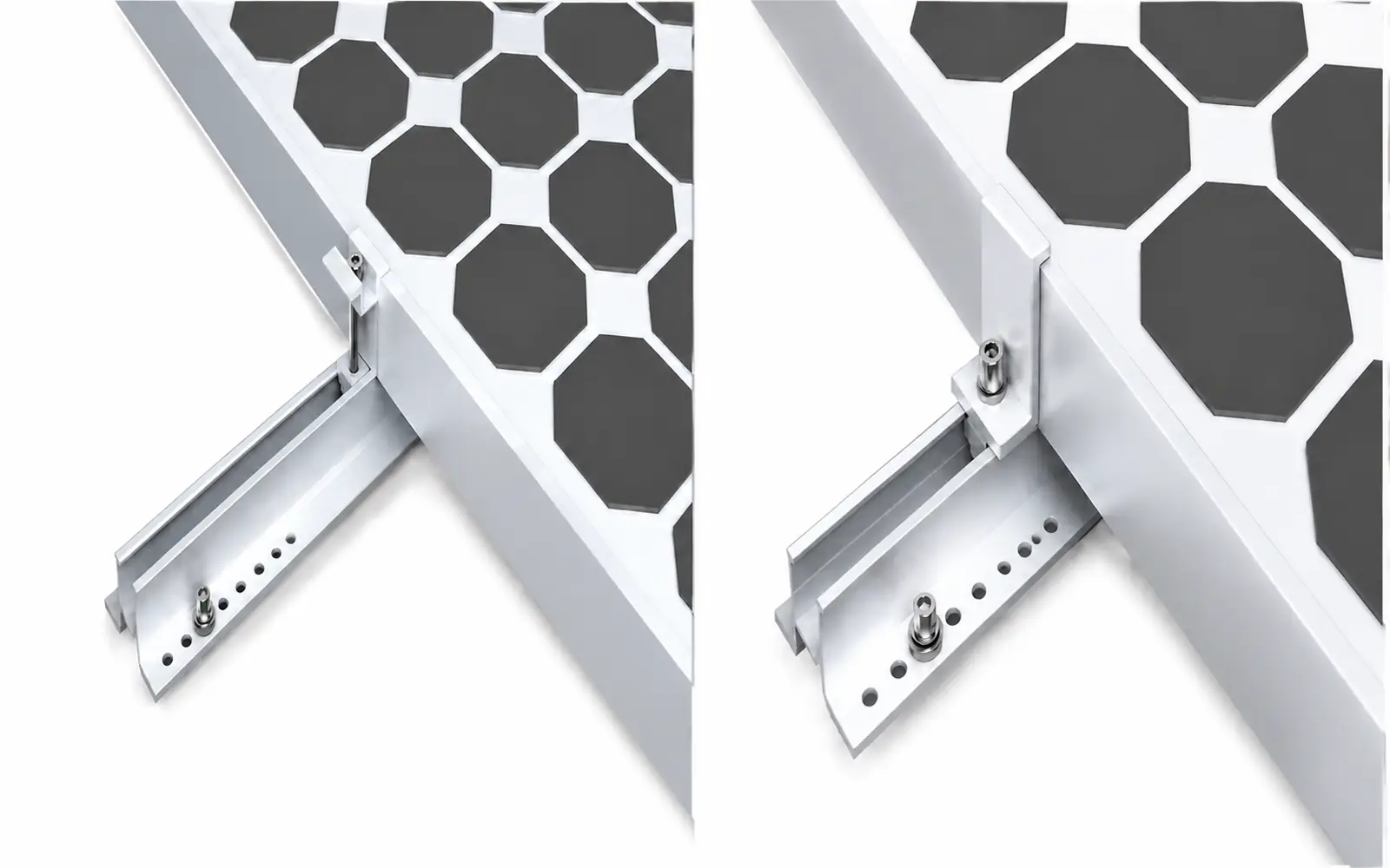
Compatibility involves more than frame height. The clamp’s shape, contact area, mounting position, fastener, and rail engagement must suit the approved assembly.
Some modules can instead be bolted through designated mounting holes or retained with other manufacturer-approved hardware. These methods need their own installation details.
See our solar panel clamps for component information.
Rails, Beams, and Frames
Rails provide the interface beneath the modules. On a ground-mounted structure, rails may connect to beams and supporting frames. A purlin is a secondary structural member that can support the modules or rails, depending on the system.
A rail clamp can secure a rail to another structural member. This serves a different connection from a module clamp, which retains the panel frame.
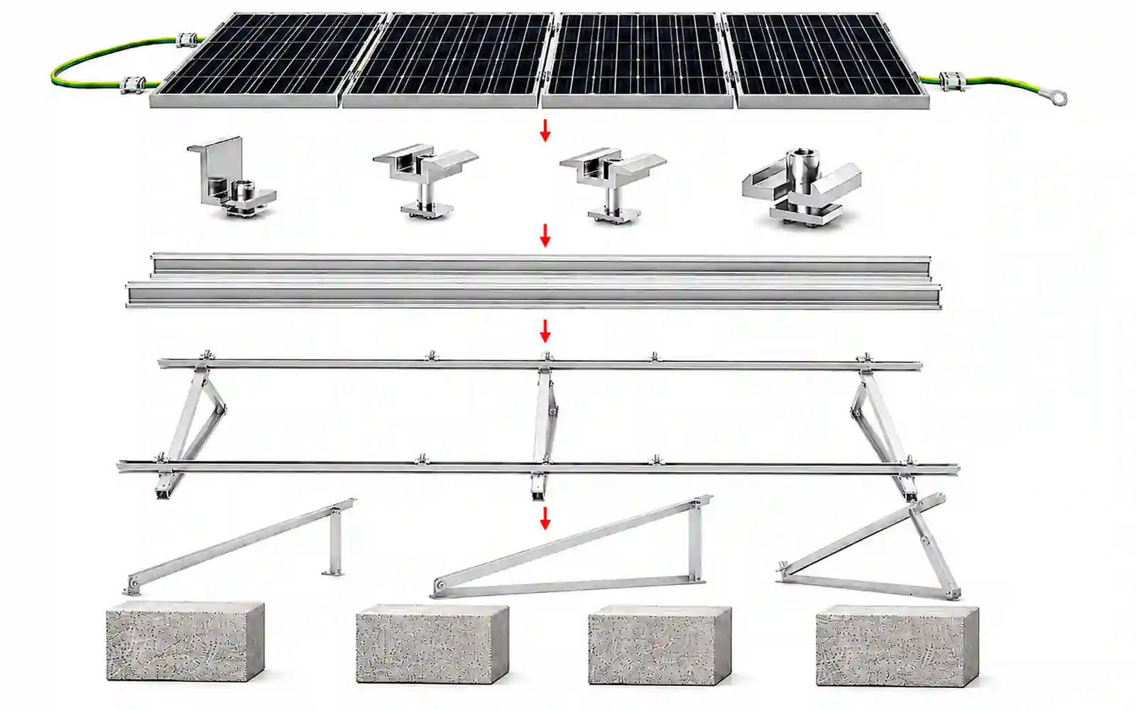
Continuous rails, mini rails, and direct-attachment systems provide different support arrangements:
| Arrangement | How the module is supported | What must match |
|---|---|---|
| Continuous rails | Clamps or approved mounting hardware engage longer rail runs | Rail profile, support positions, splices, module mounting zones, and movement details |
| Mini rails | Short rail sections provide local support and attachment interfaces | Roof profile, fastener arrangement, module orientation, and permitted support locations |
| Direct attachment | Dedicated hardware connects the module to roof-mounted supports | The complete mounting product and the module’s approved attachment method |
Mini rails are still rail sections. A direct-attachment system may eliminate separate mounting rails while using its own module-retention hardware.
For the detailed comparison, see rail-based vs railless solar mounting systems.
Roof Attachments and Ground Foundations
Roof attachments connect the array to a suitable roof assembly or structural support. Ground-mounted systems use foundations such as driven piles, ground screws, or concrete foundations, selected for the site and structural design.
Typical load paths include:
- Rail-based roof mounting: module frame → module clamp → rail → roof attachment → supporting roof structure.
- Standing-seam mounting: module → rail or direct-attachment hardware → seam clamp → roof panel and seam → roof clips or fixings → building structure.
- Ground mounting: module → clamp or approved mounting bolt → rail or purlin → supporting frame → posts and foundations → soil.
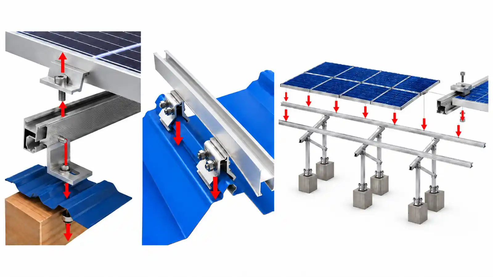
These paths explain the connections to check. Actual products may combine functions, and some foundations also serve as structural posts.
For the broader system overview, see what is solar racking?.
How Are Solar Panels Mounted on Different Roofs and Sites?
The module-retention method and the building or foundation connection need separate checks. Changing the roof or site often changes the second connection even when similar module clamps are used.
| Roof or application | Typical mounting connection | Main installation check |
|---|---|---|
| Asphalt-shingle roof | Flashed attachments, rails, and module clamps | Connection to the specified framing or approved substrate, plus integration with roof water-control layers |
| Tile roof | Tile-compatible hooks or attachments supporting rails | Structural fixing, hook clearance, tile reinstatement, and waterproofing |
| Standing-seam metal roof | Compatible seam clamps with rails or direct-attachment hardware | Seam geometry, roof construction, clamp compatibility, and roof movement |
| Corrugated or trapezoidal metal roof | Profile-specific brackets, fasteners, and rails or mini rails | The verified connection to structural members or an engineered roof-sheet assembly, plus sealing |
| Flat or low-slope membrane roof | Attached, ballasted, or hybrid supports | Roof capacity, wind resistance, membrane compatibility, drainage, and access |
| Ground-mounted array | Module supports and frames connected to foundations | Soil conditions, foundation installation, frame alignment, and connection details |
| Solar carport | Module supports on beams and columns with foundations | Structural connections, clearance, drainage, and cable routing |
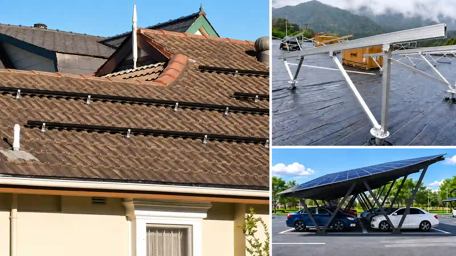
Roof Connections and Waterproofing
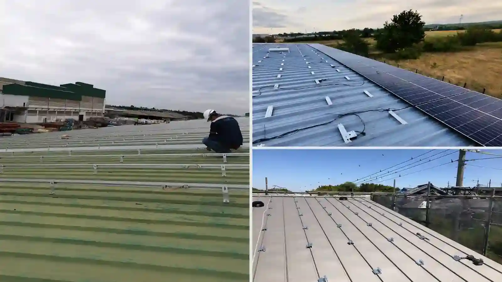
Many roof systems fix into rafters, purlins, or other structural members. Some engineered products attach to specified decking or roof panels within defined limits. The visible roof covering alone does not establish whether the attachment is suitable.
For penetrating systems, the waterproofing detail may include flashing, gaskets, bonded washers, membrane flashing, or specified sealants. The attachment must integrate with the actual roof construction. PNNL’s roof-anchor guidance explains the relationship between structural fixing and roof water-control layers.
Standing-seam clamps may avoid new roof-panel penetrations, but the seam, roof clips, panel material, and mounting arrangement still need checking. Thermal movement also depends on the roof construction; S-5!’s thermal-movement guidance explains why the actual roof assembly matters.
See solar panel roof mounting systems for system selection and our metal-roof mounting guide for roof-profile details.
Ground and Carport Connections
Ground-mounted frames transfer forces through their connections into foundations and soil. Foundation choice and installation depend on geotechnical conditions, project loads, corrosion exposure, and construction access.
Carports also require coordinated beam, column, foundation, drainage, and clearance details. The supporting structure and its connection requirements form part of the project design.
Explore our ground solar mounting systems for application-specific components.
Confirm Module Compatibility Before Installation
Use the exact module model’s installation manual, together with the mounting-system instructions and project drawings. A module datasheet provides useful dimensions and ratings, but it may not include all installation restrictions.
Check:
- Module dimensions, weight, frame height, and frame profile.
- Approved clamp positions, contact geometry, and retention method.
- Permitted mounting holes for bolted installation.
- Module orientation and the required support arrangement.
- The load limits associated with the specified installation configuration.
- Bonding and grounding requirements for the module and mounting assembly.
Keep mounting holes, grounding holes, and drainage openings distinct. Use each only for its designated purpose, and do not drill or modify the frame without the module manufacturer’s authorization.
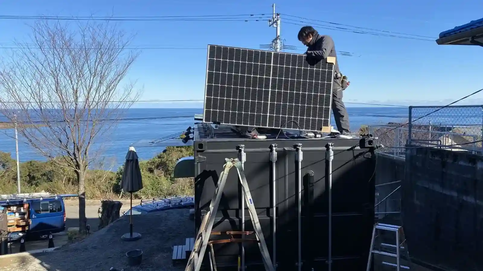
For example, the JinkoSolar installation manual requires clamps to avoid contact with the front glass and deformation of the frame, and distinguishes grounding holes from mounting holes for the modules it covers. Apply the current instructions for the actual model.
When a module changes, review the layout, supports, clamps, loads, and BOM before releasing the revised configuration.
How Are Solar Panels Mounted? The Installation Workflow
The following sequence describes the mechanical assembly and its coordination with bonding and cable management. The actual construction method follows the applicable product instructions and project documents.
1. Confirm the Documents and Mark the Layout
Before setting out the array, check that the module model, mounting products, drawing revision, and BOM describe the same assembly.
The main documents serve different purposes:
| Document | What it establishes |
|---|---|
| Module installation manual | Permitted retention methods, mounting positions, support configurations, and module-specific restrictions |
| Mounting-system instructions | Compatible components, assembly details, tightening methods, bonding provisions, and movement requirements |
| Project drawings and design documents | Site layout, attachment or foundation positions, structural requirements, and project-specific details |
| Roof manufacturer’s requirements, where applicable | Compatible waterproofing, roof interfaces, and conditions affecting the roof assembly |
Resolve conflicts or missing details before installing the affected connection.
Mark the layout against the actual site. Check support locations, roof edges, access routes, drainage, and project-required clearances.
2. Install Roof Attachments or Ground Foundations
Install roof attachments using the specified substrate, fastener arrangement, and waterproofing method. With seam clamps, check the actual seam profile and seating before tightening.
For ground arrays, locate and install foundations to the project requirements. Record installation results and any required site tests.
If the roof construction or ground conditions differ from the design inputs, obtain a reviewed detail before changing the connection.
3. Assemble Frames, Rails, and Splices
Assemble the supporting members in the required orientation. Check alignment, support spacing, rail overhangs, splice locations, and specified movement provisions.
Use the fastening method for each connection. Some joints have a specified torque; others use a defined seating or installation procedure.
For torque-controlled joints, confirm the value and unit, tool requirements, and any specified thread or lubrication condition. N·m, in-lbf, and ft-lbf are different units. Use suitable torque tools with calibration maintained under the project’s quality procedure.
Manufacturer documents such as the IronRidge XR Flush Mount installation manual illustrate why fastening requirements are assigned to individual connections.
4. Prepare Bonding and Cable Supports
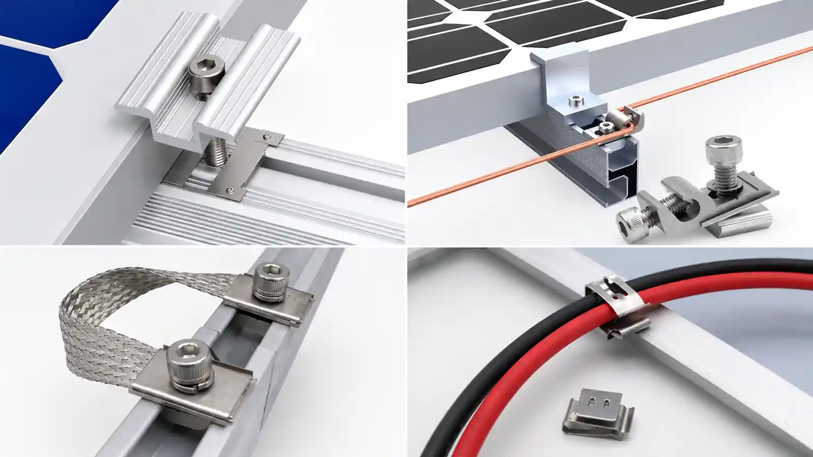
Install components that would become difficult to reach after the modules are placed. This may include selected bonding parts, cable clips, or wire supports.
Some bonding interfaces engage when the module clamp is tightened; others require separate parts or a later step. Follow the applicable assembly sequence.
Mechanical retention alone does not establish electrical bonding. The required conductive connections, grounding arrangement, and compatible hardware must be documented for the installation.
5. Position and Secure the Modules
Place each module in the required orientation and support position. Install the matching clamps or approved mounting bolts, maintaining the specified gaps and clearances.
Check that clamps contact the intended frame surface, remain within permitted mounting zones, and engage their rail or support interface correctly.
A shared mid clamp retains two neighboring frames. Its physical quantity in the BOM therefore differs from counting retention points on every individual module.
6. Complete Cable Management and Inspect the Assembly
Complete bonding and cable support according to the applicable mechanical and electrical details. Keep cables clear of sharp edges, abrasion, standing water, and moving parts.
Inspect the completed assembly against the documents:
| Connection | Applicable information | Inspection focus |
|---|---|---|
| Module to rail or support | Module manual and mounting-system instructions | Mounting position, clamp contact, hardware engagement, and module clearance |
| Rail to roof attachment or frame | System assembly detail | Matching parts, alignment, fastening method, and movement provisions |
| Rail splice | Rail installation instructions | Splice type, position, engagement, and required movement detail |
| Roof attachment to substrate | Attachment instructions and project fixing detail | Specified substrate, fastening arrangement, and waterproofing |
| Frame or base to foundation | Project connection drawing and assembly instructions | Member orientation, correct fasteners, alignment, and required installation records |
| Bonding hardware | System bonding instructions and electrical design | Compatible interfaces, required connections, and documented inspection method |
Use the specified inspection procedure for each joint. Record reviewed field changes and update the final documents to match the installation.
A Ground-Mounted Design Example: Connecting the Drawing to the BOM
A design reference from Easy Solar illustrates a ground-mounted array supported on ground screws. The drawing and accompanying project records describe:
- 2 × 7 modules per table: 14 modules.
- 20 tables: 280 modules.
- 340 W per module: 95.2 kW of nominal module capacity.
- Module dimensions: 1684 × 1002 × 30 mm.
- Tilt angle: 15°.
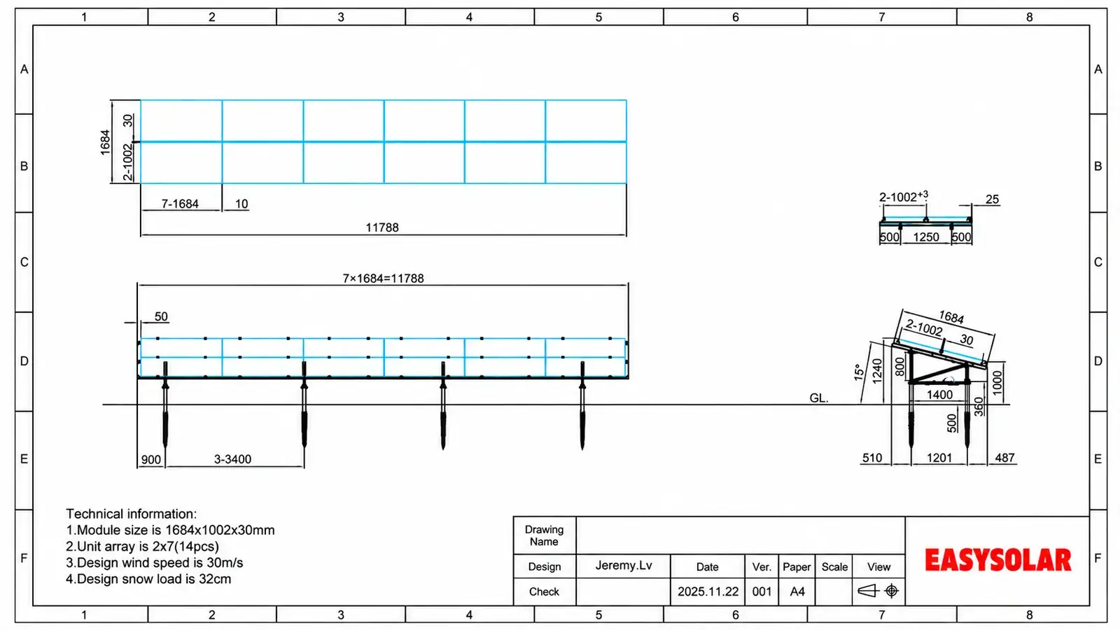
This example describes the proposed assembly recorded in the design and quotation documents.
From Ground-Mount Design to Real-World Solar Installation
The Easy Solar engineering reference demonstrates a 95.2 kW ground-mounted solar PV system designed with 280 solar panels arranged across 20 mounting tables. Each table supports 14 modules in a 2 × 7 configuration, with a 15° tilt angle and ground screw foundations.
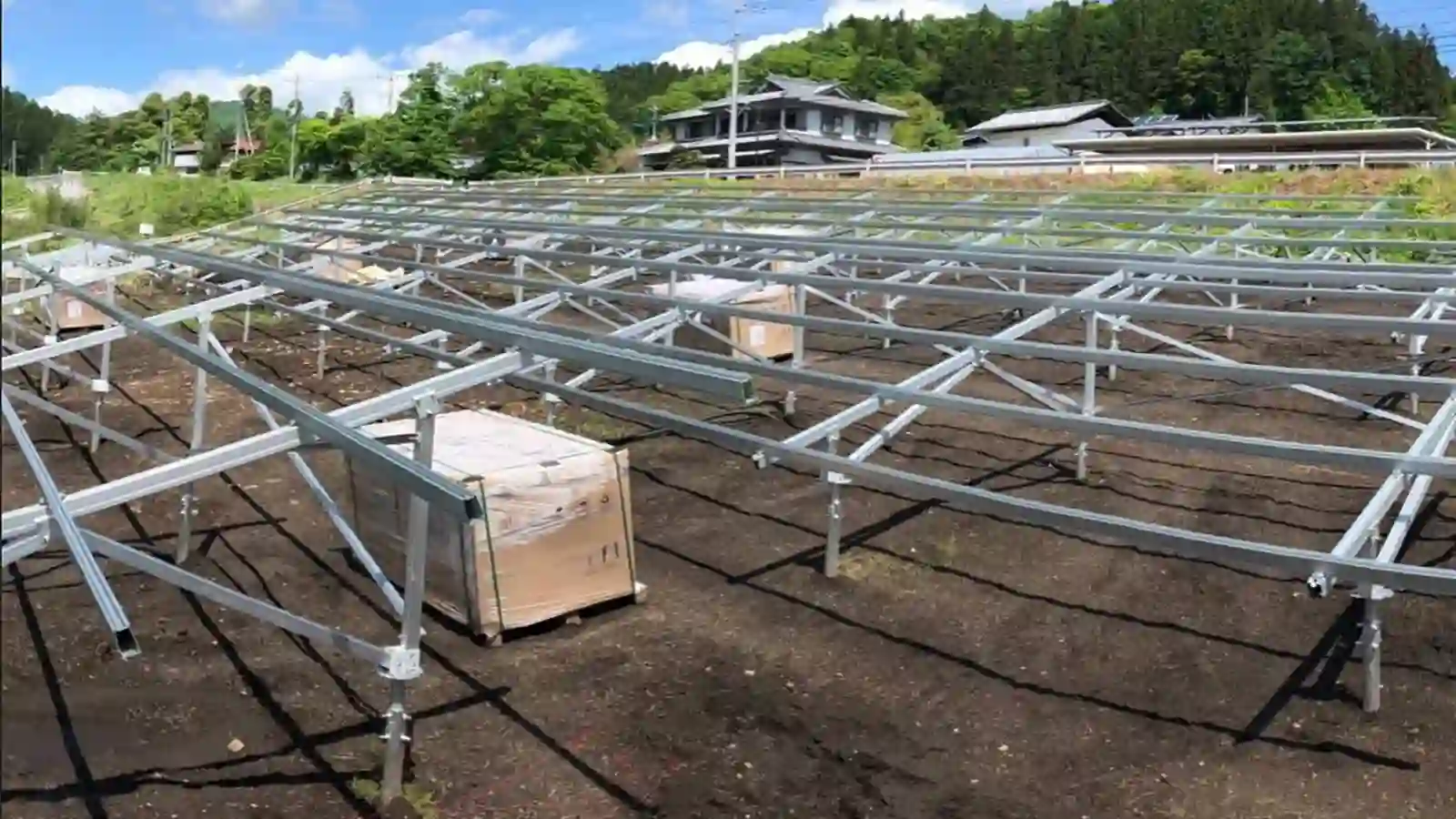
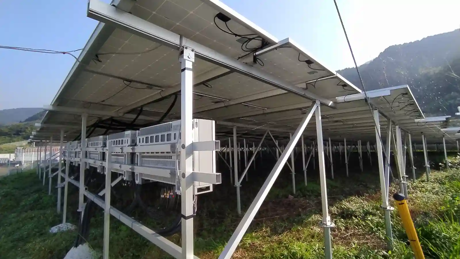
A completed ground-mounted solar array site photo provides a practical visual reference for how fixed-tilt solar mounting systems appear after installation. The finished array illustrates the relationship between solar panels, mounting rails, structural support frames, and ground-mounted foundations. These components work together to form a stable solar panel mounting structure designed around the project’s specific requirements.
For solar installers and EPC contractors, comparing engineering drawings, the bill of materials (BOM), and actual installation photos helps clarify how a ground screw solar mounting system is assembled. Easy Solar provides ground solar mounting systems and project-specific component configuration support to help customers coordinate PV mounting rails, module clamps, structural frames, and foundation connections.
Different Clamps Serve Different Connections
The drawing includes separate details for an end module clamp, a mid module clamp, and rail clamps.
The module clamps retain the panel frames on the rails. Rail clamps secure the rail to the supporting member below it. Another detail shows the connection between a structural support, base, and ground screw.
This makes the assembly easier to understand: a module clamp, rail clamp, and foundation connection perform different tasks even when they appear in the same drawing.
Selected Rail, Frame, and Foundation Line Items
The reference documents provide the following selected quantities:
| Component | Reference code | Length | Quantity per table | Quantity for 20 tables |
|---|---|---|---|---|
| Mounting rail | E001 | 3400 mm | 3 | 60 |
| Mounting rail | E001 | 4300 mm | 6 | 120 |
| Rail splice | ES-0001 | 200 mm | 6 | 120 |
| Rail clamp | ES-2001 | 40 mm | 24 | 480 |
| Main supporting beam | B002 | 2250 mm | 4 | 80 |
| Ground screw | GS-1005 | 2500 mm | 8 | 160 |
The specified rail pieces form three nominal 12,000 mm runs per table: 4300 + 3400 + 4300 mm. Two splice connections per run correspond to six rail splices per table.
This is a useful example of checking quantities against geometry. A BOM should also identify the component specification, applicable drawing revision, and assembly instructions.
These lengths and quantities belong to this reference configuration. They are not general requirements for other arrays. The drawing also states that foundation specifications must be established through geotechnical investigation or site testing.
Common Solar Panel Mounting Mistakes
Frequent coordination problems include:
- Selecting clamps by frame height without checking the complete interface.
- Using a grounding or drainage opening as a mounting hole.
- Substituting rails, clamps, or fasteners without reviewing compatibility.
- Installing roof attachments against a different substrate from the design.
- Restricting movement that the roof or mounting system is intended to accommodate.
- Applying one tightening value or procedure to different joints.
- Using a BOM that no longer matches the drawing or module model.
- Leaving cables unsupported or exposed to abrasion.
- Inspecting only visible module clamps and overlooking roof or foundation connections.
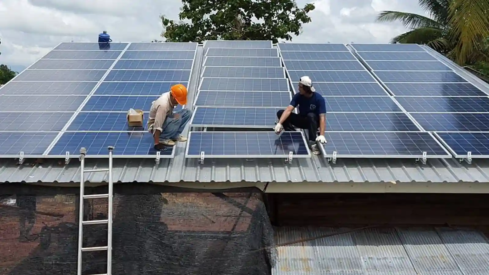
A clear drawing, matching BOM, and connection-specific inspection method help identify these issues before handover.
FAQ
Do Solar Panels Always Need Mounting Rails?
No. Systems may use continuous rails, mini rails, or dedicated direct-attachment hardware. The chosen arrangement must be compatible with the module and supporting structure.
Can Solar Panels Be Mounted Without Drilling Into the Roof?
Some compatible standing-seam systems use clamps without new roof-panel penetrations. Some ballasted systems can also avoid penetrations. Suitability depends on the roof assembly, product, wind design, and structural capacity.
How Many Clamps Does Each Solar Panel Need?
Check the module installation manual, mounting-system instructions, and project configuration. Required retention positions and clamp quantities depend on the approved method and loads. Shared mid clamps also affect the physical number of parts purchased.
Can Any Clamp Be Used With Any Rail?
Compatibility depends on the clamp, fastener, rail channel, frame profile, mounting position, and required performance. A similar appearance or matching frame height is not enough to establish suitability.
Does Every Roof Attachment Have to Fix Into a Rafter or Purlin?
Many systems connect to structural framing. Other engineered products can use specified decking or roof-panel connections within defined limits. Check the actual attachment product, substrate, and load path.
What Should Be Checked When the Module Model Changes?
Review module dimensions, weight, frame profile, mounting zones, support orientation, load limits, and bonding requirements. Then check the drawing and BOM for affected parts or layout changes.
Prepare the Right Information for a Mounting Recommendation
For an initial discussion, share the project location, application, roof or site photos, estimated module quantity, and available module information.
As the configuration develops, the review may also require the final module installation manual, array layout, and wind and snow design inputs. For roof projects, include building height and roof construction. For ground projects, share available soil and foundation information.
Wind speed, wind pressure, snow depth, and snow load are different inputs. Identify their units, meaning, and applicable design basis when available.
Easy Solar provides preliminary engineering and configuration support for component matching and quotation preparation. Drawings, BOM information, and other outputs depend on the project stage and agreed scope. Project-specific structural approval and final compliance responsibilities must also be established for the project.
Send Your Module Datasheet and Site Details for a Mounting Recommendation

Sales Manager at Easy Solar Solar Mounting Systems. With over 1o years of experience in the solar industry, I specialize in providing reliable andcost-effective mounting solutions for distributors, installers, and EPC companies. Experienced in intemational sales and commited to building long-term partnerships worldwide.