
How Are Solar Panels Mounted? From Structure to Module Clamp
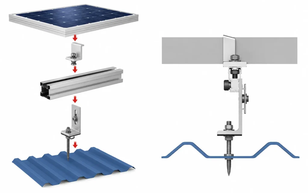
Solar panels are not simply “bolted to a roof” or “placed on a frame.” In a professional PV installation, each module is held by a chain of structural interfaces that transfers loads from the module into the roof, ground, or supporting canopy.
In a typical rail-based system, that chain looks like this:
PV Module → Module Clamp → Mounting Rail or Purlin → Bracket / Structural Frame → Roof Attachment or Foundation → Building or Ground
The exact components change by application. A tile roof may use roof hooks, a standing seam roof may use seam clamps, a ground-mounted system may use posts and driven piles, and a carport may use columns and beams. But the basic job is the same: support the module, position it correctly, restrain it against wind and other loads, maintain the required electrical bonding, and provide a practical route for cables.
DOE describes PV mounting structures as the durable structural support that must carry the array and resist environmental effects over the life of the system.
This guide explains how mounting solar panels actually works from the supporting structure to the final module clamp, including the parts that change between roof, ground, and carport systems and the interfaces that remain similar.
For a broader introduction to PV racking, see What Is Solar Racking?. For product categories, see Solar Mounting Systems.
The Six Layers of Solar Panel Mounting
A useful way to understand a solar panel mounting system is to separate it into six layers.
| Mounting Layer | Typical Components | Main Function |
|---|---|---|
| 1. Supporting Surface | Roof structure, soil, concrete slab, carport frame | Receives the final structural loads |
| 2. Primary Attachment | Roof hook, L foot, seam clamp, hanger bolt, pile, ground screw, anchor | Connects the racking to the supporting surface |
| 3. Structural Frame | Posts, beams, rafters, braces, tilt legs, rail clamp | Creates the main PV support geometry |
| 4. Module Support | Aluminum rail, purlin, mini rail, direct-attach support | Supports and aligns the module |
| 5. Module Retention | Mid clamp, end clamp, frame bolt, fastener | Secures the PV module to the support |
| 6. Electrical & Cable Interface | Bonding hardware, grounding lugs, cable clips, cable tray | Maintains electrical continuity and cable support |
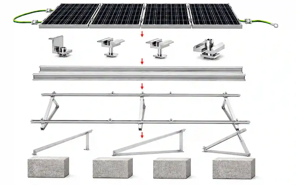
Not every project uses all six layers as separate components.
A rail-less roof system may combine the primary attachment and module-support functions. A ground structure may use a purlin instead of an aluminum rail. A tracker may connect the module directly to tracker-specific supports.
PNNL likewise notes that conventional rooftop PV often uses rails with panels clamped to them, while some systems eliminate the rail layer altogether.
The key is to understand the function of each interface rather than assuming every solar module mounting system uses the same parts.
1. Solar Panels Start with the Supporting Structure
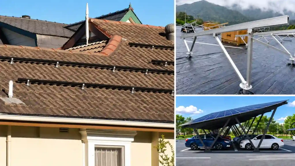
Before selecting rails or clamps, the project needs to identify what ultimately supports the PV array.
Roof-Mounted Solar Panels
On a rooftop, the supporting structure may include:
- Timber rafters
- Roof trusses
- Steel purlins
- Structural deck
- Standing seam roof assemblies
- Concrete roof slabs
The roof covering itself is not always the final structural support.
For example, a tile roof hook usually passes below the tile and connects to the roof structure. A metal-roof bracket may connect through the sheet to a purlin, while a compatible standing seam clamp can grip the seam without creating a new roof penetration.
PNNL recommends selecting rooftop racking around roof type, module compatibility, weatherproofing, and wind and snow loading, with the attachment integrated into the roof structure and water-control system.
For roof applications, see Roof Solar Mounting Systems.
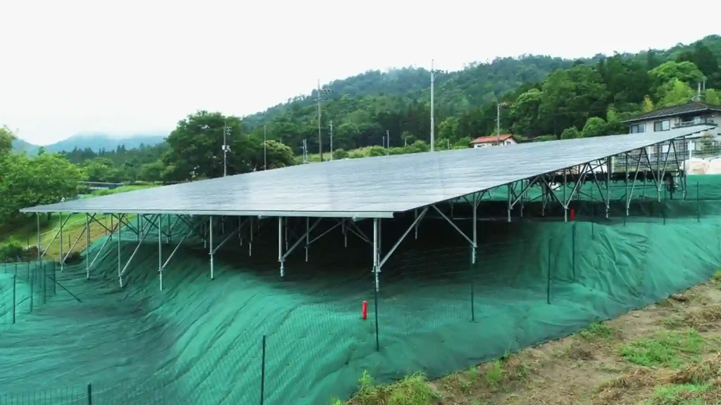
Ground-Mounted Solar Panels
A ground-mounted array creates its own supporting structure.
The soalr ground mounting system may include:
- Driven piles
- Ground screws
- Concrete foundations
- Posts
- Beams
- Braces
The soil and foundation are therefore part of the complete solar module mounting structure.
DOE treats ground-mounted PV as structurally distinct from rooftop and carport projects and includes site, foundation, racking and fastener considerations in its installation guidance.
For ground applications, see Ground Solar Mounting Systems.
Solar Carports
A solar carport combines PV mounting with a canopy structure.
The structural path can include:
- Concrete foundations
- Steel or aluminum columns
- Main beams
- Purlins or mounting rails
- Module clamps
Unlike a simple ground rack, the structure also has to preserve vehicle clearance, drainage, parking access, and other canopy requirements.
2. The Primary Attachment Connects the Racking to the Site
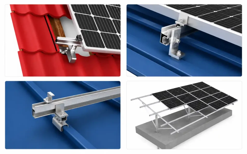
The primary attachment is the first mechanical interface between the mounting system and the supporting structure.
This component changes more than almost any other part of the system.
Common Roof Attachments
Depending on the roof, mounting solar panels may involve:
- Tile roof hooks
- L feet
- Hanger bolts
- Flashed roof anchors
- Trapezoidal roof brackets
- Corrugated roof brackets
- Standing seam clamps
- Triangle solar brack
- Adjustable solar panel mount
- Mini rail
- Ballasted solar rack
- Concrete foundation solar mounting system
The correct attachment must match both the roof covering and the structural support below it.
Water management also becomes part of the attachment design whenever the roof is penetrated. PNNL specifically identifies flashing and sealing of roof penetrations as part of appropriate PV mounting-system design.
Common Ground Attachments
For ground-mounted systems, the primary attachment is usually a foundation.
Typical options include:
- Driven steel piles
- Ground screws
- Concrete blocks
The foundation must transfer compression, uplift, lateral force, and other structural reactions into the ground.
Why the Attachment Comes Before the Rail
A common purchasing mistake is to choose the rail first and then look for a bracket that can connect it to the project.
The better sequence is:
Supporting Structure → Attachment Method → Structural Geometry → Rail / Purlin → Module Clamp
The rail needs to work as part of the attachment and structural system rather than being selected as an isolated component.
3. The Structural Frame Creates the Module Geometry
Once the primary attachment is established, the mounting structure creates the position, tilt, spacing, and support geometry for the PV modules.
On a roof, the structural frame may be minimal. Roof attachments can connect directly to rails or short mounting profiles.
On a ground mount or carport, the frame is much more visible and can include posts, beams, rafters, braces, and purlins.
The structural frame determines:
- Module orientation
- Tilt angle
- Row geometry
- Ground or roof clearance
- Support spacing
- Rail or purlin span
- Module-table size
- Maintenance access
DOE emphasizes that racking and frame elements need to withstand project environmental loads, and that frames with vertical members may require lateral bracing to resist movement.
A solar module mounting structure design should therefore start with the module and project geometry rather than treating the upper frame as a generic steel or aluminum rack.
4. Rails and Purlins Form the Module Support Interface
The next layer is the surface that directly supports or locates the modules.
In many systems, this is an aluminum mounting rail.
Solar Panel Mounting Rails can provide:
- A continuous module support line
- Alignment across multiple modules
- A channel for module clamps
- A connection point for roof attachments or structural brackets
- A location for rail splices
- An interface for selected grounding and cable-management hardware
Penn State’s commercial PV course similarly identifies rails, splices and clamps as key mechanical BOS components connecting PV modules to the mounting structure.
Ground and carport structures may also use steel or aluminum purlins rather than conventional rooftop rail profiles.
The important engineering question is not whether the component is called a “rail” or “purlin.”
The question is:
How does the module connect to it, and how does it transfer load to the next structural layer?
Rail-Based Mounting
A traditional rail-based system creates a continuous support line beneath multiple modules.
This can provide useful installation adjustment and alignment.
Typical components include:
- Rails
- Rail splices
- Roof or structural brackets
- T-bolts or channel hardware
- Mid clamps
- End clamps
Mini-Rail and Rail-Less Mounting
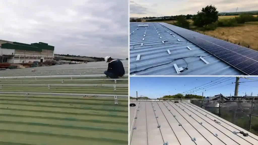
Some roof systems use short rails or direct-attach hardware.
These systems reduce the quantity of long rail but make local attachment position and module compatibility especially important.
Rail-less does not mean structure-less.
It means one structural layer has been shortened, combined, or replaced by another engineered interface. PNNL also recognizes rooftop systems that eliminate the conventional rail layer while retaining the required mounting and attachment functions.
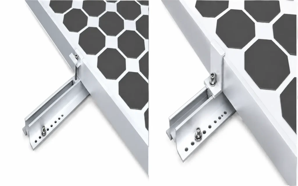
5. The Module Is Positioned in Its Approved Mounting Zone
The solar module itself is a structural component.
Its aluminum frame is designed to transfer loads from the module into the mounting system at defined support or clamping locations.
Before installing the module, confirm:
- Module model
- Module dimensions
- Frame thickness
- Approved clamp zones
- Approved mounting holes, if bolted mounting is used
- Portrait or landscape orientation
- Rail or purlin spacing
- Required support configuration
This is one reason the final module should be confirmed before the mounting bill of materials is released.
A change in module length, width, frame thickness, or approved mounting zone can change:
- Rail spacing
- Clamp selection
- Support position
- Table dimensions
- Attachment layout
- Component quantities
The mounting system should follow the module manufacturer’s installation documentation rather than assuming every framed PV module can be clamped in the same location. PNNL likewise recommends verifying compatibility between the chosen racking system and the PV modules and following the relevant product documentation.
6. Mid Clamps and End Clamps Secure the Modules
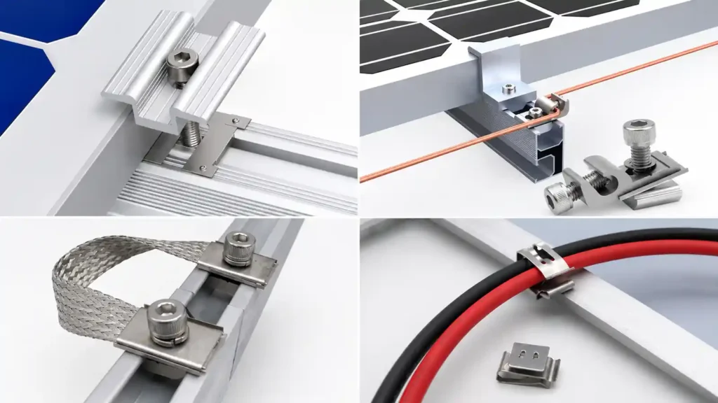
For many framed PV systems, the final mechanical connection is the module clamp.
Solar Panel Clamps are typically divided into two main categories.
Mid Clamps
Mid clamps are installed between adjacent modules.
A typical mid clamp engages the frames of two neighboring modules and secures both to the same rail or support profile.
Mid clamps can also help establish consistent module-to-module spacing.
End Clamps
End clamps secure the outside edge of the first and last module in a row.
The clamp must match the module frame thickness and the mounting profile.
What a Module Clamp Actually Does
A module clamp is not just a piece that prevents the panel from sliding.
It is part of a structural connection.
The clamp has to:
- Engage the module frame correctly
- Fit the rail or support profile
- Remain in the approved module mounting zone
- Achieve the required installation torque
- Maintain the intended connection under project loads
- Work with the system’s bonding or grounding strategy where applicable
This is why visually similar clamps should not automatically be substituted without checking dimensions, fasteners, rail interface, module compatibility, and system requirements.
DOE’s severe-weather guidance identifies module-to-racking connections as critical fastened joints and records field failures associated with poor installation, inadequate strength, vibration-induced loosening, joint relaxation, and failed module mid-clamps.
7. Fasteners Hold the Interfaces Together
A solar mounting system contains many fastened joints.
Depending on the design, these can include:
- Module clamp bolts
- T-bolts
- Channel nuts
- Structural bolts
- Rail splice bolts
- Roof attachment fasteners
- Hanger bolts
- Self-drilling screws in approved applications
- Anchor bolts
- Foundation connection bolts
Each fastener belongs to a specific interface.
For example:
Clamp bolt → module-to-rail interface
T-bolt → rail-to-bracket interface
Structural bolt → beam-to-post interface
Anchor bolt → column-to-foundation interface
This interface-based view is useful because a fastener should not be selected only by diameter or material.
Thread engagement, joint geometry, preload, locking method, corrosion environment, and the connected materials all matter.
DOE describes critical fastened joints as integral to module mounting, racking-frame connections, roof attachments, foundations and carport structures.
Installation torque should follow the selected mounting-system and component documentation. One generic torque value should not be used across unrelated joints. PNNL specifically recommends that bolted connections be torqued according to the PV-system manufacturer’s requirements.
8. Grounding and Bonding Are Part of the Mounting System
The mounting structure is mechanical, but it also interacts with the electrical safety system.
Metal module frames, rails, clamps, and structural components may need to be bonded so that exposed conductive parts maintain the required electrical continuity.
Depending on the system, components can include:
- Grounding clips
- Bonding washers
- Grounding lugs
- Bonding jumpers
- Listed module-clamp bonding features
- Grounding conductors
This is why the clamp, rail, surface coating, and grounding hardware should be considered together.
An anodized rail, painted steel member, stainless fastener, and aluminum module frame can all be mechanically connected while still requiring a verified bonding method.
UL Solutions states that UL 2703 covers mounting systems, mounting devices, clamping/retention devices and ground lugs used with flat-plate PV modules and panels, illustrating how mechanical mounting, bonding and grounding are treated as an integrated safety system.
9. Cable Management Should Be Planned Before the Modules Hide the Structure
Cable management is often treated as the final cleanup step.
It should be planned earlier.
Once modules cover the rails and structural members, some cable routes become difficult to reach.
A complete solar mounting layout should consider:
- Module lead length
- String routing
- MLPE or microinverter position where used
- Cable clips
- Rail-based cable support
- Cable tray
- Transition points
- Sharp edges
- Moving components on trackers
- Drainage paths
- Maintenance access
Cables should not be left resting on the roof or ground where they can experience abrasion, standing water, sharp edges, movement, or maintenance damage.
DOE’s current cable-management guidance recommends supporting and routing DC-string wiring to prevent damage and addresses premature failure of unsuitable cable ties.
For larger projects, cable support can become part of the structural coordination between the mounting system and the electrical installation.
How the Mounting Chain Changes by Application
The upper part of the mounting chain is often similar across project types, while the lower part changes dramatically.
| Application | Primary Support | Typical Attachment | Module Support | Module Retention |
|---|---|---|---|---|
| Tile Roof | Roof rafters / structure | Roof hooks | Aluminum rails | Mid / end clamps |
| Metal Roof | Purlins, deck, or standing seam system | L feet, hanger bolts, profile brackets, seam clamps | Long rail, mini rail, or direct attach | Module clamps / direct hardware |
| Flat Roof | Roof deck / building structure | Ballast, anchors, or hybrid supports | Tilt frame / rails | Module clamps |
| Ground Mount | Soil / foundation | Driven pile, ground screw, concrete | Posts + beams + rails / purlins | Module clamps / bolts |
| Solar Carport | Concrete foundation + canopy structure | Anchor / column connection | Beams + purlins / rails | Module clamps / bolts |
DOE separately identifies rooftop, ground-mounted and carport PV as project types with different installation and structural considerations.
The module may be identical in all five projects.
What changes is the structure below it.
This is an important procurement principle:
Module compatibility alone does not define a mounting system.
The roof, foundation, supporting frame, and project loads determine the lower structural interfaces.
Rail-Based vs Direct-Attach: Where Does the Rail Go?
Not every PV module is mounted to a long aluminum rail.
There are three broad architectures.
Rail-Based
Module → Clamp → Rail → Attachment / Frame
This is common because rails provide continuous alignment and adjustment.
Short-Rail or Mini-Rail
Module → Clamp → Short Rail → Roof Attachment
This reduces long rail material and can be useful on selected metal roofs.
Direct-Attach or Rail-Less
Module → Direct Mounting Hardware → Roof Clamp / Structural Support
This removes or combines the conventional long-rail layer.
The architecture should be selected as a complete system.
Removing one component does not remove its structural function; that function has to be performed by another component or interface.
A Professional Installation Sequence
For a typical project, mounting solar panels follows a sequence similar to this:
Step 1: Confirm the Final Module
Verify module dimensions, frame, orientation, mounting zones, and quantity.
Step 2: Confirm the Supporting Surface
Identify roof structure, soil/foundation requirements, or carport structural frame.
Step 3: Select the Primary Attachment
Choose the appropriate roof attachment, foundation, clamp, bracket, or anchor.
Step 4: Set the Structural Geometry
Confirm tilt, table layout, row spacing, support spacing, and access.
Step 5: Install the Primary Structure
Install roof attachments, foundations, posts, beams, brackets, or tilt frames according to the approved project design.
Step 6: Install Rails or Module Supports
Align the rails, purlins, mini rails, or direct-mount supports.
Step 7: Coordinate Grounding and Cable Routes
Install or prepare bonding parts, cable support, MLPE interfaces, and cable paths before access is restricted by the modules.
Step 8: Position the Modules
Place modules according to the approved orientation and mounting zones.
Step 9: Install Module Clamps or Bolted Connections
Secure modules using the specified hardware and installation torque.
Step 10: Perform Final Inspection
Check structural connections, module alignment, clamp position, torque requirements, grounding, cable support, waterproofing where relevant, and visible installation damage.
DOE’s current installation guidance similarly treats racking, fasteners, electrical equipment, cable management, commissioning and documentation as related parts of the installation process rather than isolated tasks.
The exact construction sequence will differ by system, but the interface logic remains the same.
Why Mounting Drawings and BOMs Matter
A solar mounting system is not just a box of hardware.
The drawing explains where the components go. And the BOM explains what components and quantities are required.
They should define interfaces such as:
- Module-to-clamp
- Clamp-to-rail
- Rail-to-bracket
- Bracket-to-roof
- Beam-to-post
- Post-to-foundation
- Rail-to-splice
- Rail-to-grounding component
This is particularly important for project procurement.
Two mounting systems may both contain rails, clamps, brackets, and bolts, but those parts are not necessarily interchangeable.
A correct BOM should match the final:
- Module
- Layout
- Supporting structure
- Attachment method
- Wind and snow requirements
- Corrosion environment
- Structural drawing
- Installation method
This section intentionally addresses searches around solar module mounting structure design and mounting drawings without turning the article into a downloadable generic drawing that could be incorrectly applied to an unrelated project.
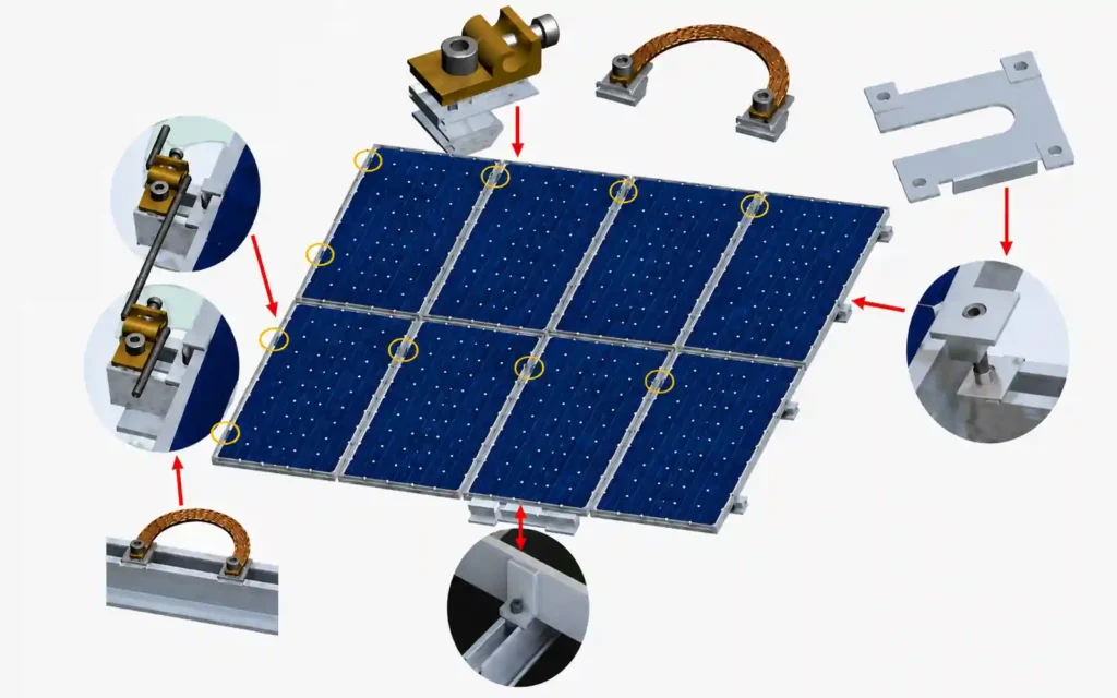
Common Mounting Mistakes
Selecting Components Individually Instead of as Interfaces
A clamp may fit the module but not the rail.
A rail may fit the bracket but not meet the required support spacing.
A bracket may fit the roof profile but connect poorly to the underlying structure.
The complete interface chain should be reviewed together.
Changing the Module Without Updating the Racking
Module size and mounting zones influence rail spacing, clamps, structure dimensions, and quantities.
Treating the Roof Covering as the Entire Structure
The visible roof surface may not be the member that carries the PV loads.
Using One Clamp for Every Module Frame
Clamp dimensions, frame thickness, mounting zone, bolt length, and rail interface can vary.
Using Generic Torque Values
Different fastened joints have different installation requirements.
DOE field guidance documents chronic fastener loosening and other connection vulnerabilities as real PV-system risks, which is why joint-specific installation requirements matter.
Adding Grounding After Mechanical Installation
Bonding should be coordinated with the racking architecture and listed system requirements.
Leaving Cable Management Until the End
Once modules are installed, some cable-support locations are difficult to access.
Focusing Only on Dead Weight
PV mounting systems also need to resist wind, snow, vibration, movement, and other project-specific actions. DOE specifically requires mounting structures to be designed for long-term environmental exposure and appropriate project loads.
What Information Is Needed to Define the Mounting System?
For a professional quotation or preliminary mounting configuration, provide:
| Project Information | Why It Matters |
|---|---|
| Project type | Determines roof, ground, carport, balcony, or other architecture |
| Roof / site information | Defines primary attachment or foundation |
| PV module datasheet | Defines size, frame, mounting zones, weight |
| Module quantity | Determines layout and component quantities |
| Portrait / landscape layout | Changes support geometry |
| Wind requirement | Affects attachments, rails, structure, fasteners |
| Snow requirement | Affects spans and support layout |
| Tilt / roof slope | Defines module geometry |
| Structural spacing | Rafters, purlins, posts, or other support locations |
| Corrosion environment | Influences material and finish |
| Drawings / photos | Helps confirm interfaces |
| Packaging / delivery scope | Helps prepare project BOM and shipment |
A supplier can then evaluate the mounting system as a connected assembly rather than quoting rails and clamps separately.
Common Questions About Mounting Solar Panels
How are solar panels mounted?
Most framed solar panels are secured to a solar pv mounting system using module clamps. The module support then transfers loads through rails, beams, brackets, structural frames, roof attachments, or foundations into the supporting building or ground.
Do solar panels always need mounting rails?
No.
Many systems use rails, but selected metal-roof and other mounting architectures can use mini rails or rail-less direct-attach systems.
What holds solar panels onto the rails?
Framed PV modules are commonly held by mid clamps between adjacent modules and end clamps at the outside edges of a module row.
Other systems may use bottom clamps, direct-attach hardware, or bolts through approved module-frame mounting holes.
What is the difference between a mounting bracket and a module clamp?
A mounting bracket usually connects the rail or racking structure to the roof, frame, or another structural support.
A module clamp secures the PV module frame to the rail or module-support structure.
They work at different interfaces.
Are solar panels bolted directly to a roof?
Usually not in a conventional rail-based system.
The roof attachment connects to the building structure, a rail connects to that attachment, and the module is then clamped to the rail. PNNL describes this two-rail-and-clamp architecture as a common rooftop mounting arrangement.
Some direct-attach systems combine or eliminate the long-rail layer.
Are solar panels bolted directly to the ground?
No.
Ground-mounted PV modules are supported by a racking frame, which transfers loads into foundations such as driven piles, ground screws, or concrete.
Why are mid clamps and end clamps different?
Mid clamps secure adjacent modules between their frames. End clamps secure the outer edge of the first or last module in a row.
Can any solar clamp fit any module?
No. The solar clamps need to be matched to the specific panel and rail types.
The clamp should match the module frame, approved mounting zone, rail interface, fastener, and the requirements of the selected mounting system.
Why does mounting torque matter?
The fastener preload helps create the intended structural joint. If the torque is too low, the solar mounting structure may loosen or shift, reducing stability and creating safety risks. If the torque is too high, the bolts, threads, or mounting components may be damaged or deformed, potentially leading to connection failure. So torque should follow the mounting-system and component documentation. We recommend that using manufacturer-specified torque for PV bolted connections.
Is grounding part of the solar mounting system?
Yes.
PV mounting systems often incorporate bonding and grounding components or listed bonding functions at module, clamp, rail, or racking interfaces. UL 2703 covers mounting systems together with clamping/retention devices and ground lugs.
What is the most important thing to check before ordering solar mounting hardware?
Confirm the complete interface chain:
module → supporting structure → attachment method → rail or purlin → clamp → fastener → grounding method → project loads.
Think in Interfaces, Not Individual Parts
The simplest answer to “how are solar panels mounted?” is:
They are connected through a sequence of engineered interfaces from the module frame to the supporting roof, ground, or structure.
The module clamp is only the final visible connection.
Below it may be a rail, purlin, roof bracket, structural frame, foundation, or building member. Alongside it are fasteners, grounding components, waterproofing details, and cable supports that allow the complete system to work as one installation.
For EPC contractors, installers, distributors, and project developers, the best way to specify mounting hardware is therefore not to purchase isolated brackets and clamps.
Start with the final module and project conditions, define each connection in the structural chain, and build the BOM around compatible interfaces.
Explore Solar Mounting Systems for roof, ground, carport, agrivoltaic, and balcony mounting solutions.
For component-level selection, see Solar Panel Mounting Rails and Solar Panel Clamps.
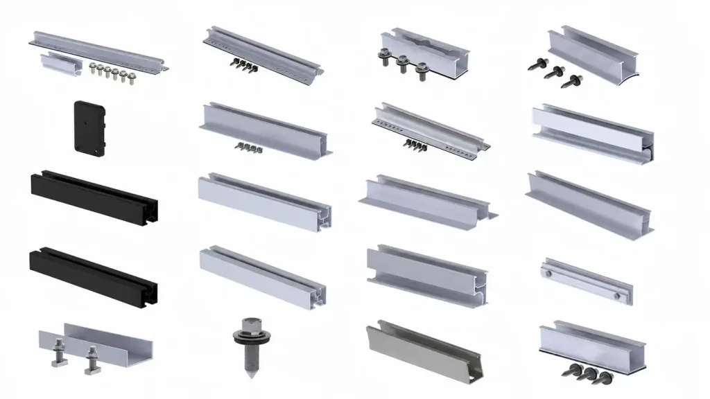
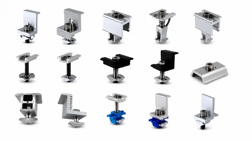
For a project-specific mounting configuration, send your project details including module data, roof or site information, layout, wind and snow requirements, tilt and available drawings.
References & Technical Sources
- U.S. Department of Energy — Solar Photovoltaic System Design Basics
https://www.energy.gov/cmei/systems/solar-photovoltaic-system-design-basics - U.S. Department of Energy — Life Cycle of Photovoltaic Systems: Install and Commission a Photovoltaic System
https://www.energy.gov/cmei/femp/life-cycle-photovoltaic-systems-install-and-commission-photovoltaic-system - U.S. Department of Energy — Severe Weather Resilience in Solar Photovoltaic System Design
https://www.energy.gov/cmei/femp/severe-weather-resilience-solar-photovoltaic-system-design - Pacific Northwest National Laboratory / Building America Solution Center — Roof Anchor System for Solar Panels
https://basc.pnnl.gov/resource-guides/roof-anchor-system-solar-panels - UL Solutions — PV Mounting Systems Certification / UL 2703
https://www.ul.com/services/pv-mounting-systems-certification - U.S. Department of Energy — PV System Owner’s Guide to Identifying, Assessing, and Addressing Weather Vulnerabilities, Risks, and Impacts
https://www.energy.gov/cmei/femp/articles/pv-system-owners-guide-identifying-assessing-and-addressing-weather

Sales Manager at Easy Solar Solar Mounting Systems. With over 1o years of experience in the solar industry, I specialize in providing reliable andcost-effective mounting solutions for distributors, installers, and EPC companies. Experienced in intemational sales and commited to building long-term partnerships worldwide.