
How to Mount Solar Panels on a Metal Roof
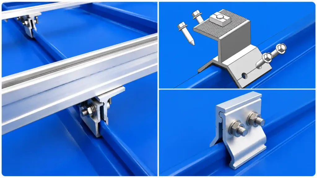
Mounting solar panels on a metal roof starts with one decision that affects almost everything that follows: identify the roof profile before selecting the attachment hardware.
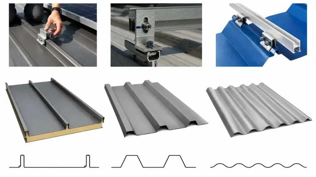
Standing seam, trapezoidal, corrugated, and other exposed-fastened metal roofs can all support PV systems, but they do not use the same mounting method. A compatible standing seam roof can often use seam clamps without creating new roof penetrations. Corrugated and trapezoidal roofs more commonly use mechanically fastened brackets, L feet, hanger bolts, mini rails, or other profile-specific attachments with an appropriate sealing detail.
For professional projects, the objective is not simply to fasten a solar panel to sheet metal. The complete system must transfer module, wind, and snow loads through the mounting hardware into an approved supporting structure while maintaining roof weather protection and component compatibility.
If you need the broader roof-mounting context first, read Solar Panel Roof Mounting Systems. You can also review What Is Solar Racking? and Types of Solar Mounting Systems for the wider mounting-system framework.
For metal-roof product options, see Metal Roof Solar Mounting System.
Metal Roof Solar Mounting at a Glance
The first selection can usually be organized around roof profile and attachment strategy.
| Metal Roof Type | Common Mounting Approach | New Roof Penetration | Typical Module Support |
|---|---|---|---|
| Standing Seam | Seam clamp | Often avoidable on compatible seams | Rail-based, mini rail, or direct attach |
| Trapezoidal Metal Roof | Profile bracket, L foot, hanger bolt, or mini rail | Common in many systems | Long rail, mini rail, or direct attach |
| Corrugated Metal Roof | Hanger bolt, L foot, or corrugated-profile bracket | Common in many systems | Rail-based or selected compact system |
| Other Exposed-Fastened Metal Roof | Mechanically fastened roof attachment | Usually required | Rail-based or roof-specific direct mount |
| Low-slope Metal Roof | Triangle solar mount, adjustable solar panel mount | Usually required | Rail-based or direct attach |
The table is a starting point, not a substitute for project engineering. Roof geometry, sheet thickness, structural support, module layout, attachment capacity, wind, snow, corrosion environment, and waterproofing requirements still need to be confirmed.
Step 1: Identify the Metal Roof Profile
The most common mistake when mounting solar panels on a metal roof is choosing the hardware before confirming the roof profile.
The roof profile determines how the attachment sits on the surface, where the structural fastener can be placed, whether a non-penetrating clamp is possible, and how water moves around the mounting point.
Standing Seam Metal Roof
Standing seam roofs use raised vertical seams with concealed panel fasteners. Because the seams project above the roof surface, compatible clamps can often grip the seam mechanically without drilling through the roof panel.
This makes standing seam one of the most distinctive metal roof solar mounting applications.
However, standing seam is not one universal geometry. Seam height, width, fold shape, snap-lock or mechanically seamed construction, metal thickness, and panel manufacturer can all affect clamp compatibility.
Before selecting a seam clamp, please supply the clear roof photos, a roof-panel profile drawing or seam dimensions.
The standing seam metal roof usually use the standing seam clamps, also use the standing seam clamp with L feet according to the requirements.
Trapezoidal Metal Roof
Trapezoidal roofs use raised ribs with relatively flat sides and flat pans between the ribs. They are common on commercial, industrial, warehouse, and agricultural buildings.
A trapezoidal roof can use several mounting strategies, including:
- L feet
- Hanger bolts
- mini rails
- Direct-attach systems designed for the roof profile
Bracket geometry should fit the rib correctly. The mounting design also needs to consider sheet thickness, fastener location, structural support below the panel, and the sealing method.
Corrugated Metal Roof
Corrugated metal roofing has a rounded wave-like profile.
Because the attachment surface is curved, a corrugated metal roof solar mount may use a hanger bolt, L foot, bridge-style bracket, or another mounting component shaped for the roof geometry.
The attachment should sit correctly on the profile without creating an unstable bearing point or an unsuitable sealing surface.
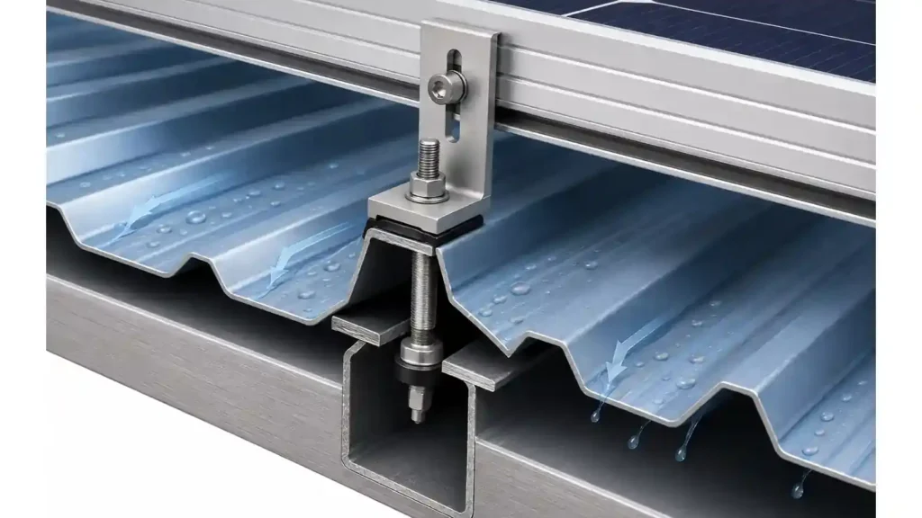
Where the mounting fastener penetrates the sheet, the project needs a compatible water-management detail.
Other Exposed-Fastened Metal Roofs
Exposed-fastened roofs use visible screws through the roof sheet. The solar mounting attachment may also be mechanically fastened through the panel, but the existing roof screw should not automatically be treated as the PV structural attachment.
The solar load path must be understood separately.
Depending on the system, the mounting fastener may connect to a purlin, rafter, deck, or another approved structural element. Some engineered direct-attach systems can use the roof panel differently, but that should be based on the specific system design rather than assumption.
Low-slope Metal Roof
Low-slope Metal Roof can use the triangle solar mount or adjustable solar panel mount expect for the the standing seam clamps, L feet, mini rail.
Step 2: Choose the Metal Roof Solar Mounting Method
Once the solar mounting system is confirmed, the next decision is the attachment family.
The main methods are standing seam clamps, L-foot-and-rail systems, hanger-bolt systems, and compact mini-rail or direct-attach systems.
Standing Seam Clamps
A compatible standing seam clamp grips the seam mechanically.
The clamp can then support an aluminum rail, short rail, or system-specific direct module attachment.
The main advantage is the possibility of avoiding new penetrations through the metal roof panel. This can simplify water management because no new hole is intentionally created at the clamp location.
The important limitation is compatibility.
A clamp should not be selected only because it appears to fit over the seam. The seam geometry, clamp interface, required holding capacity, installation torque, attachment spacing, and project loads should all be checked according to the selected mounting system.
Future detailed guidance can compare different standing seam clamp arrangements, but for a general metal roof project the first requirement is simply to identify the exact seam before ordering hardware.
L Feet and Rail-Based Mounting
L feet create an adjustable connection between the roof attachment and the mounting rail.
A simplified rail-based load path is:
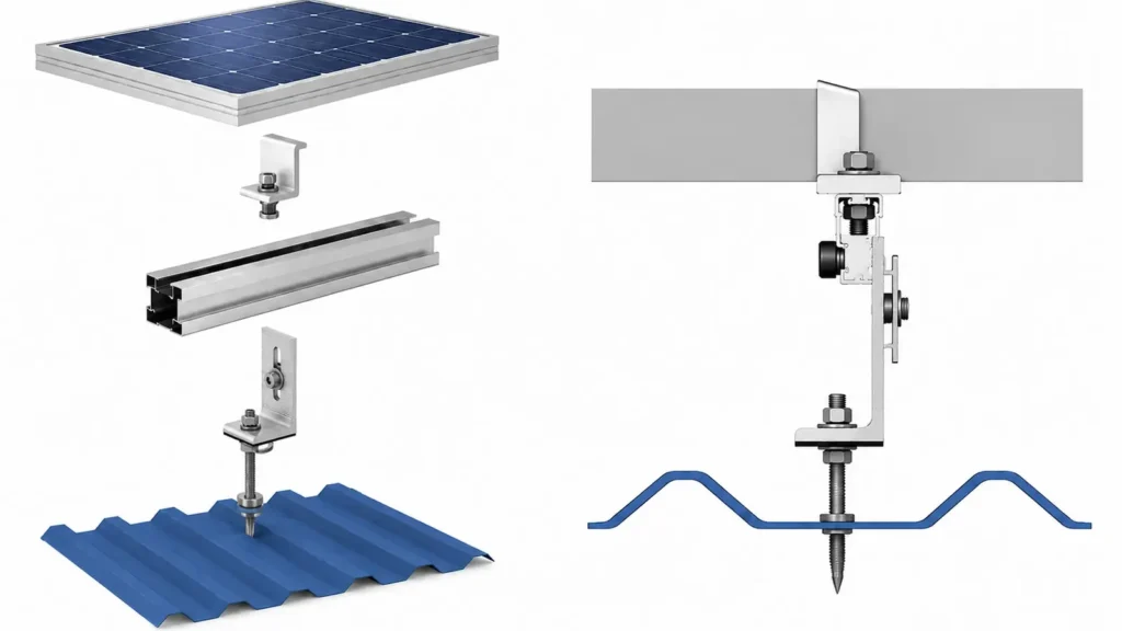
PV Module → Module Clamp → Aluminum Rail → L Foot / Roof Attachment → Purlin, Rafter, or Other Approved Structure
L-foot systems are widely used because they provide rail-height adjustment and a familiar structural interface.
They can be combined with different roof attachments depending on the roof profile. For example, the L foot may connect to a mechanically fastened metal-roof bracket or to a hanger-bolt assembly.
The final attachment, fastener, and sealing detail should match the actual roof and supporting structure.
Hanger Bolt Systems
Hanger bolts are commonly used on selected corrugated and trapezoidal roofs.
A typical assembly can include:
- Hanger bolt
- Sealing washer or EPDM component
- Adapter plate or L foot
- Aluminum rail
- Mid and end clamps
- Connection fasteners
The structural portion of the hanger bolt must connect to an approved supporting member or follow the specific engineered attachment design.
Hanger-bolt selection therefore depends on more than the visible roof sheet. Thread type, structural substrate, embedment, sealing, adapter geometry, and required load all matter.
Mini Rails and Direct-Attach Brackets
Selected metal roofs can use short rails, mini rails, or compact direct-attach brackets instead of long continuous rails.
Potential advantages include:
- Less long-rail material
- Easier rooftop handling
- Smaller shipping packages
- Fewer rail splices
- A lower-profile mounting assembly
However, reducing rail length does not remove structural requirements.
Attachment spacing, module mounting zones, roof profile, sheet or substrate connection, thermal movement, wind loads, and module compatibility still need to be reviewed.
A mini-rail system should therefore be selected as a complete mounting architecture rather than as a shorter substitute for any conventional rail.
Step 3: Verify the Roof Structure and Roof Condition
The visible metal sheet is only one layer of the roof.
Before the final solar mounting layout is prepared, confirm what carries the structural loads below it.
Depending on the building, this may include:
- Steel purlins
- Timber rafters
- Structural decking
- Secondary steel members
- Standing seam clips
- Other engineered support members
Purlin or rafter spacing can directly affect attachment placement.
The roof condition also matters. Inspect for corrosion, damaged seams, loose or aged roof fasteners, deformed panels, coating damage, and existing leakage.
Installing a new PV array over a roof that needs major repair can create unnecessary removal and reinstallation work later.
For older commercial roofs, the remaining roof service life should be considered before the array is installed.
Step 4: Confirm the PV Module and Array Layout
Metal roof solar mounts cannot be finalized without module information.
At minimum, confirm:
- Module manufacturer and model
- Module length and width
- Frame thickness
- Module weight
- Approved mounting zones
- Portrait or landscape orientation
- Modules per row
- Number of rows
- Array dimensions
The module dimensions affect rail spacing, clamp location, attachment layout, row length, and material quantities.
This becomes particularly important with large-format modules.
If the module changes after the first design, the mounting system should be checked again before production. A different frame size or mounting zone can change clamps, rails, attachment positions, and the complete bill of materials.
Step 5: Plan the Attachment Layout for Wind and Snow Loads
Attachment spacing should not be copied from another project simply because the roof looks similar.
The correct layout depends on the interaction between:
- Module dimensions
- Rail or support span
- Roof attachment capacity
- Purlin or rafter spacing
- Roof height and geometry
- Array position
- Wind conditions
- Snow conditions
- Edge and corner zones
- Applicable structural requirements
Wind can create uplift, downward pressure, and lateral forces.
Roof edges, corners, parapets, and rooftop obstructions can also influence local wind behavior. As a result, some areas of an array may require a different attachment density or structural configuration from other areas.
Snow adds gravity load and can influence rail span, clamp position, support spacing, and structural reactions.
For this reason, one generic statement such as “suitable for X m/s wind” should not replace project-specific mounting design.
Step 6: Manage Roof Penetrations and Waterproofing
Water management is one of the most important differences between metal roof mounting methods.
Non-Penetrating Standing Seam Mounting
When a compatible standing seam clamp is used, no new hole is intentionally drilled through the roof panel at the clamp location.
This can preserve the roof’s continuous water-shedding surface.
The key controls become seam compatibility, correct clamp installation, structural holding capacity, spacing, and the selected rail or direct-attach interface.
Penetrating Metal Roof Attachments
Corrugated, trapezoidal, and other exposed-fastened metal roofs commonly use mechanically fastened attachments.
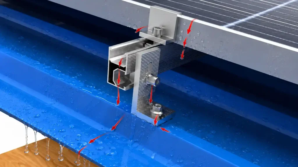
Where a fastener penetrates the roof sheet, the attachment should include a suitable sealing and water-management method.
Depending on the roof and mounting product, components can include:
- EPDM sealing washers
- Rubber sealing pads
- Butyl materials
- Flashing components
- Profile-matched sealing interfaces
- Other roof-compatible weatherproofing parts
The structural fastener and the waterproofing function should both be correct.
Sealant alone should not be used to compensate for an unsuitable attachment geometry or poor structural connection.
The mounting point also should not block normal drainage or create a location where water is intentionally trapped around the attachment.
Step 7: Install Rails, Mini Rails, or Direct Module Supports
After the roof attachments are positioned and checked, the module-support structure can be installed.
Long-Rail Systems
Long aluminum rails provide a continuous support and alignment interface.
They make it easier to adjust module rows and provide standard locations for mid clamps, end clamps, rail splices, grounding parts, and cable-management accessories.
For rail-based projects, see Solar Panel Mounting Rails.
During layout, review:
- Rail direction
- Rail span
- Rail splice location
- Attachment spacing
- Module clamp positions
- Rail overhang
- Thermal movement
- Cable-routing requirements
Rails should be aligned before module installation rather than using the module clamps to compensate for major layout errors.
Mini-Rail and Direct-Attach Systems
Compact systems use shorter support profiles or direct module interfaces.
They can simplify material handling, but their localized support points make accurate placement particularly important.
The system should follow the approved module mounting zones and the attachment spacing required for the project loads.
Rail-based and compact systems should therefore be compared on total project suitability, not only aluminum weight.
Step 8: Install and Clamp the PV Modules
Framed PV modules are commonly secured with mid clamps and end clamps.
Solar Panel Clamps must match both the module frame and the rail.
Mid clamps are typically positioned between adjacent module frames, while end clamps secure the outside edges of a module row.
Before final tightening, check:
- Module alignment
- Clamp engagement
- Correct clamp position
- Module mounting zone
- Required installation torque
- Row spacing
- Cable clearance
Do not assume that a clamp designed for one frame thickness automatically works with another module.
If the array uses a direct-attach or rail-less system, the module connection should follow that system’s approved hardware and mounting points.
Step 9: Complete Grounding, Bonding, Cable Management, and Final Inspection
The mechanical installation is not complete when the last module clamp is tightened.
The mounting system also has to coordinate with grounding, bonding, cable routing, and future maintenance.
Depending on the project design, the mounting assembly may use:
- Grounding clips
- Bonding washers
- Grounding lugs
- Cable clips
- Cable trays or other cable-support systems
PV cables should be supported so they do not rest loosely on the metal roof, rub against sharp edges, interfere with drainage, or hang where wind movement can cause abrasion.
Before completion, inspect:
- All roof attachments
- Clamp and rail connections
- Required fastener torque
- Seal and washer condition
- Rail or module alignment
- Grounding and bonding components
- Cable support
- Drainage clearance
- Roof damage created during installation
Project documentation should record any required inspection or torque checks according to the mounting system and applicable project requirements.
Rail-Based vs Rail-Less Metal Roof Solar Mounting
Both approaches can work well when used in the correct application.
| Factor | Rail-Based | Mini-Rail / Rail-Less |
|---|---|---|
| Module Alignment | High adjustment flexibility | More dependent on attachment placement |
| Long Material Handling | More long rails | Reduced |
| Rail Splices | May be required | Reduced or eliminated |
| Attachment Accuracy | Important | Especially important |
| Module Compatibility | Rail and clamp dependent | System-specific interface |
| Typical Metal Roof Use | Standing seam, corrugated, trapezoidal | Selected standing seam and profile roofs |
| Cable Support Options | Often flexible along rail | Needs system-specific planning |
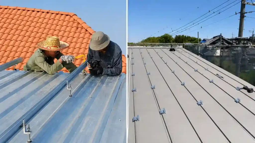
The correct choice depends on roof geometry, module dimensions, project loads, installation workflow, material logistics, and the mounting products available for the roof.
Corrosion and Material Compatibility
A metal roof PV installation can combine several materials in one outdoor assembly.
Common examples include:
- Coated steel or aluminum roof panels
- Anodized or mill-finish aluminum mounting rails
- Aluminum roof brackets
- Stainless-steel bolts and nuts
- Galvanized structural members
- EPDM or other sealing materials
Material compatibility becomes more important in coastal, industrial, humid, and other corrosive environments.
When requesting a quotation, provide the project location and environmental conditions rather than considering only the physical dimensions of the mounting brackets.
The supplier can then review materials, finishes, fasteners, and sealing components as part of the complete solar panel mounting hardware package.
Common Mistakes When Mounting Solar Panels on a Metal Roof
1. Treating Every Metal Roof as the Same
Standing seam, trapezoidal, and corrugated roofs have different attachment interfaces.
Hardware selection should start with the roof profile.
2. Assuming One Standing Seam Clamp Fits Every Seam
Seam geometry varies by roof system.
Use photos, dimensions, or a roof-profile drawing to confirm compatibility.
3. Creating Unnecessary Penetrations in a Compatible Standing Seam Roof
Where a suitable seam-clamp system can meet the structural requirements, adding unnecessary roof penetrations removes one of the main advantages of standing seam mounting.
4. Fastening Without Understanding the Structural Load Path
A visible metal panel is not automatically the final supporting structure.
The mounting design needs to define how loads reach the purlin, rafter, deck, seam system, or other approved support.
5. Using a Penetrating Bracket Without a Proper Sealing Detail
The roof attachment must achieve both structural connection and suitable water management.
6. Using Generic Attachment Spacing
Attachment spacing depends on project loads, roof structure, mounting-system capacity, and array geometry.
7. Ignoring Corrosion or Existing Roof Damage
A mounting system should not hide or worsen a roof condition that requires repair.
8. Using an Old BOM After the PV Module Changes
Module dimensions and mounting zones can affect the complete racking layout.
Update the mounting BOM after a major module or layout revision.
9. Ignoring Cable Management
Loose cables on a metal roof can be exposed to abrasion, heat, water, and sharp edges.
Plan cable support as part of the mounting system.
What Information Should You Send a Metal Roof Solar Mounting Supplier?
For professional B2B projects, complete roof information speeds up system selection and reduces repeated clarification.
| Project Information | Why It Matters |
|---|---|
| Roof photos | Helps identify standing seam, trapezoidal, corrugated, or other profiles |
| Roof-profile drawing or dimensions | Supports clamp or bracket matching |
| Roof sheet material and thickness | Helps review attachment compatibility |
| Seam height and width | Important for standing seam clamp selection |
| Rib dimensions | Important for trapezoidal and corrugated mounting |
| Purlin / rafter type and spacing | Helps define structural attachment positions |
| PV module datasheet | Confirms module dimensions, frame, weight, and mounting zones |
| Module quantity and layout | Determines rails, supports, clamps, and attachment quantities |
| Wind information | Influences structural loads and attachment spacing |
| Snow information | Influences downward loads and support spans |
| Project location | Supports environmental and engineering review |
| Corrosion environment | Helps select materials and finishes |
| Penetration restrictions | Affects attachment strategy |
| Estimated quantity / delivery scope | Supports BOM, packing, and quotation planning |
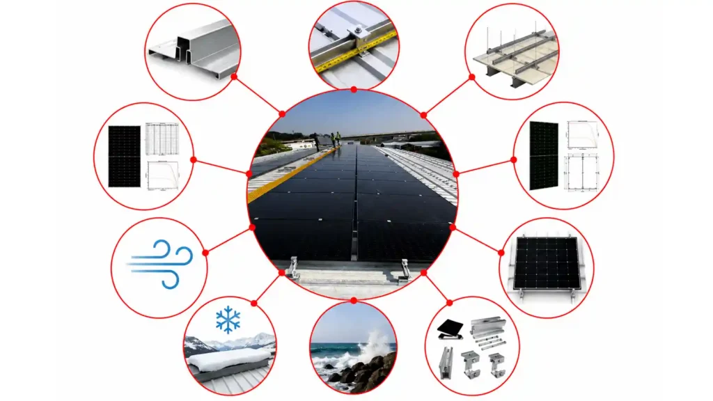
A useful quotation request should therefore include more than the phrase “solar panel mounting brackets for metal roof.”
The more complete the roof and module information, the easier it is to prepare a project-specific mounting configuration.
Common Questions About Metal Roof Solar Mounting
Can solar panels be mounted on a metal roof?
Yes. Suitable standing seam, trapezoidal, corrugated, and other metal roofs can support PV systems using roof-specific clamps, brackets, rails, hanger bolts, mini rails, or direct-attach hardware.
The roof condition, structural support, module layout, and project loads still need to be reviewed.
Can solar panels be mounted on a metal roof without drilling?
On compatible standing seam metal roofs, a seam clamp can often attach without creating a new penetration through the roof panel.
This should not be generalized to corrugated or trapezoidal roofs, which commonly use mechanically fastened attachments.
What is the best solar mount for a standing seam metal roof?
A compatible non-penetrating seam clamp is usually one of the first options to evaluate.
The correct clamp depends on seam geometry, roof material, mounting architecture, attachment spacing, and project loads.
What is a common corrugated metal roof solar mount?
Corrugated metal roofs commonly use hanger bolts, L feet, profile-compatible brackets, and rail-based mounting.
The correct approach depends on corrugation shape, structural support, sealing method, and project requirements.
What mounting systems are used on trapezoidal metal roofs?
Common options include profile-specific brackets, L feet, hanger bolts, mini rails, and selected direct-attach systems.
Rib dimensions and structural connection should be confirmed before hardware is selected.
Do solar panels on metal roofs need mounting rails?
Not always.
Traditional rail-based systems use long aluminum rails, while selected standing seam and profiled-metal systems can use mini rails or rail-less / direct-attach solutions.
How are roof leaks prevented around solar mounts?
Where the mounting method avoids roof penetration, such as a compatible standing seam clamp, no new hole is intentionally created at the clamp location.
Where penetrations are required, the mounting point should use a roof-compatible sealing and water-management detail such as appropriate washers, pads, flashing, or other system-specific components.
Do metal roof solar mounts need to attach to purlins?
Many mechanically attached systems transfer loads into purlins, rafters, or another approved structural member.
Other engineered roof-specific systems may use a different load path.
The attachment method should follow the actual mounting design.
Can the same bracket be used on corrugated and trapezoidal roofs?
Not automatically.
The profiles have different geometry, so bracket fit, sealing, structural connection, and fastener position need to be checked for the actual roof.
What information is needed for a metal roof solar mounting quotation?
Provide roof photos, roof profile or dimensions, sheet material and thickness, seam or rib dimensions, purlin information, module datasheet, array layout, project location, wind and snow requirements, and estimated quantity.
Select the Right Metal Roof Solar Mounting System
Successful mounting solar panels on a metal roof begins with matching the attachment method to the roof profile.
Standing seam roofs may allow compatible non-penetrating clamps. Corrugated and trapezoidal roofs commonly use mechanically fastened brackets, L feet, hanger bolts, or mini rails with suitable structural and sealing details.
The best system is not simply the one with the fewest components.
It is the system that:
- Fits the actual metal roof profile
- Transfers loads through a defined structural path
- Maintains appropriate roof water management
- Matches the PV module
- Meets project wind and snow requirements
- Uses compatible materials and fasteners
- Can be installed, inspected, and maintained efficiently
Explore Metal Roof Solar Mounting System for commercial metal-roof mounting options.
You can also review Solar Mounting Accessories for rails, clamps, brackets, fasteners, grounding parts, and related hardware.
For a project-specific mounting proposal, send your project details with roof photos, profile dimensions, module data, layout, and available wind and snow information.
References & Technical Sources
- Pacific Northwest National Laboratory / Building America Solution Center — Roof Anchor System for Solar Panels
https://basc.pnnl.gov/resource-guides/roof-anchor-system-solar-panels - Pacific Northwest National Laboratory / Building America Solution Center — Metal Roofs
https://basc.pnnl.gov/resource-guides/metal-roofs - U.S. Department of Energy — Severe Weather Resilience in Solar Photovoltaic System Design
https://www.energy.gov/cmei/femp/severe-weather-resilience-solar-photovoltaic-system-design - Pacific Northwest National Laboratory / Building America Solution Center — Flashing of Penetrations in Existing Roofs
https://basc.pnnl.gov/resource-guides/flashing-penetrations-existing-roofs - U.S. Department of Energy — Life Cycle of Photovoltaic Systems: Install and Commission a Photovoltaic System
https://www.energy.gov/cmei/femp/life-cycle-photovoltaic-systems-install-and-commission-photovoltaic-system

Sales Manager at Easy Solar Solar Mounting Systems. With over 1o years of experience in the solar industry, I specialize in providing reliable andcost-effective mounting solutions for distributors, installers, and EPC companies. Experienced in intemational sales and commited to building long-term partnerships worldwide.